Investment casting tolerance calculation establishes how much a manufactured metal part can deviate from its design dimensions while remaining acceptable for function, assembly, and performance.
For precision metal components used in aerospace, automotive, medical, and industrial equipment, understanding tolerance calculation is essential to achieving quality outcomes and controlling cost.
What Is Investment Casting Tolerance?
In manufacturing, tolerance refers to the acceptable variation from a specified dimension. In investment casting, where molten metal replaces wax patterns inside a ceramic shell, tolerances account for variations due to material behavior, thermal effects, and tooling precision.
These tolerances define acceptable ranges for features like diameters, wall thickness, hole locations, and form controls. Realistic tolerances ensure parts meet performance requirements while controlling inspection complexity and production costs.
Basic Concepts in Tolerance
Before exploring how to calculate tolerance, it’s useful to understand a few foundational concepts:
Nominal Dimension
The nominal dimension is the ideal or target size specified in the design documentation or CAD model.
Actual Dimension
The actual dimension is the measured size of a physical part after casting and any finishing operations.
Tolerance Band
Tolerance is typically expressed as a band around the nominal:
Plus/Minus Format: e.g., Ø50.00 ± 0.10 mm means the part can range between 49.90 mm and 50.10 mm.
Limit Format: e.g., 49.90 / 50.10 mm.
Geometric Tolerances
Geometric tolerances control aspects of shape and relation rather than size alone, including flatness, roundness, perpendicularity, and concentricity.
Understanding these concepts is essential for sound tolerance calculation.
Typical Tolerance Ranges in Investment Casting
Investment casting tolerances vary by feature size, material, and geometric complexity. The following tables provide commonly referenced tolerance ranges based on production experience in precision casting, measured on as-cast parts before any post-machining.
Dimensional Tolerance Table
| Nominal Dimension (mm) | Typical Tolerance (± mm) | Remarks |
| Up to 10 | 0.08 | Small features |
| 10–25 | 0.10 | Small to medium |
| 25–50 | 0.15 | Mid-range dimensions |
| 50–100 | 0.25 | Larger components |
| 100–200 | 0.40 | Structural parts |
| >200 | 0.60–0.80 | Very large features |
These ranges reflect typical capabilities in well-controlled casting environments. Actual supplier capability may vary.
Geometric Tolerance Table
| Geometric Feature | Typical Tolerance Range | Typical Application |
| Flatness | 0.05–0.15 mm | Mating surfaces |
| Roundness | 0.03–0.10 mm | Cylindrical bores |
| Perpendicularity | 0.05–0.15 mm | Feature orientation |
| Concentricity | 0.05–0.15 mm | Rotating parts |
| Parallelism | 0.05–0.15 mm | Opposed surfaces |
These geometric tolerances complement dimensional tolerance by ensuring essential surface relationships are within acceptable variation.
How Investment Casting Tolerance Is Calculated
Tolerance calculation in investment casting involves understanding functional requirements, referencing process capability, and assigning tolerance bands for each critical dimension. Here’s a structured approach:
Step 1: Identify Critical Dimensions
Not all dimensions are equally important. Start by determining which features affect function, assembly, or performance. Examples include:
- Bearing fits
- Sealing surfaces
- Shaft diameters
- Mounting flange flatness
These features often require tighter tolerances than secondary attachment points or non-critical surfaces.
Step 2: Establish Nominal Dimensions
Nominal dimensions derive from design intent or CAD specifications. They serve as the target for tolerance calculation.
Step 3: Reference Process Capability
Using baseline tolerance tables (as shown above) or supplier capability data, determine what variance is realistic for the casting process before post-machining. These tolerance bands are frequently based on:
- Nominal size ranges
- Material and behavior during solidification
- Typical foundry precision level
Step 4: Assign Tolerance Bands
Assign tolerances to each critical dimension based on functional need and process capability. Tight tolerances are reserved for dimensions with direct functional impact, while broader tolerances apply to non-critical features.
Step 5: Factor in Geometric Tolerances
In addition to size tolerances, include geometric tolerances where shape or orientation affects function.
Step 6: Review and Collaborate
Collaborate with suppliers and quality engineers to verify that calculated tolerances are achievable and to adjust values based on detailed process data.
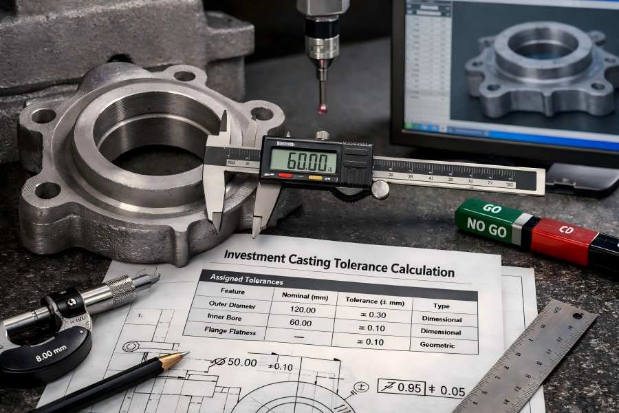
Example of Tolerance Calculation
Let’s walk through a detailed example illustrating tolerance calculation for a precision gear housing. Suppose a component has the following key features:
- Outer diameter (OD): nominal 120.00 mm
- Inner bore (IB): nominal 60.00 mm
- Wall thickness (WT): nominal 8.00 mm
- Mounting flange flatness: surface required for sealing
- Bolt circle diameter (BCD): nominal 85.00 mm
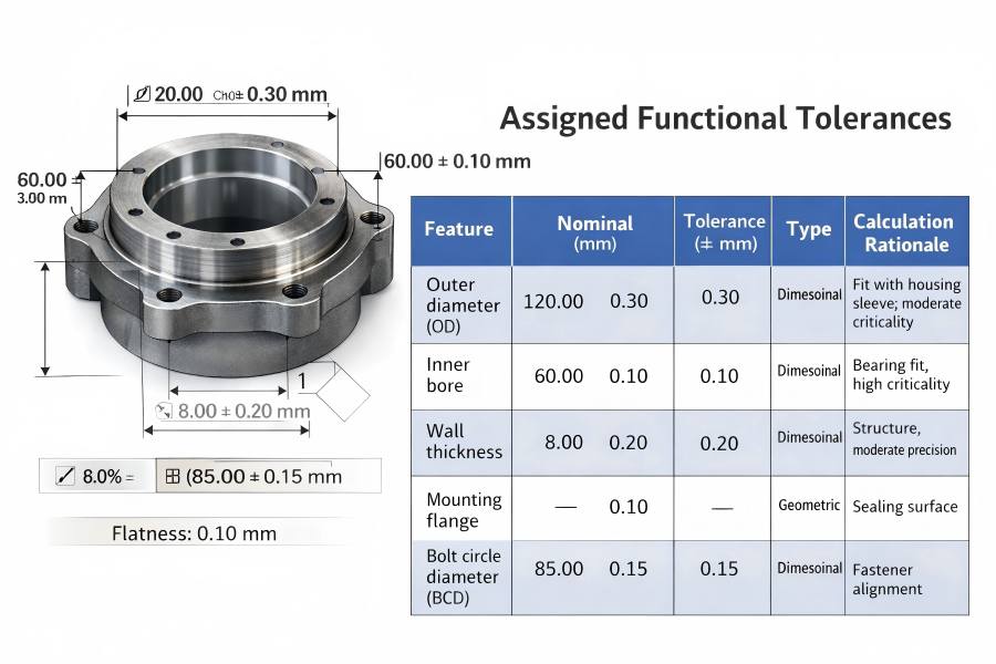
Assigned Functional Tolerances
The table below shows the tolerance assignment based on functional needs and casting process capability:
| Feature | Nominal (mm) | Tolerance (± mm) | Type | Calculation Rationale |
| Outer diameter (OD) | 120.00 | 0.30 | Dimensional | Fit with housing sleeve; moderate criticality |
| Inner bore (IB) | 60.00 | 0.10 | Dimensional | Bearing fit, high criticality |
| Wall thickness (WT) | 8.00 | 0.20 | Dimensional | Structure, moderate precision |
| Mounting flange flatness | — | 0.10 | Geometric | Sealing surface |
| Bolt circle diameter (BCD) | 85.00 | 0.15 | Dimensional | Fastener alignment |
This example blends dimensional and geometric tolerances to reflect real casting needs and process capabilities.
Factors That Influence Tolerance Calculation
Tolerance outcomes depend on more than nominal size alone. Several influencing factors shape what tolerance a foundry can realistically achieve.
Part Geometry
Complex shapes, slender walls, and abrupt cross-section changes all challenge tolerance control. Differential cooling rates lead to uneven shrinkage and variation.
Designers should aim for:
- Uniform wall thickness
- Smooth transitions between features
- Reduced cross-section variance
These design practices make tolerance control more predictable.
Material Characteristics
Different alloys solidify and shrink in distinct ways:
- Stainless steels often have predictable shrinkage behavior.
- Nickel alloys may require broader tolerance allowances due to higher shrink rates.
- Titanium and exotic alloys may have wide thermal variation affecting tolerance.
Material behavior must inform tolerance assignment.
Tooling Precision
Wax dies and ceramic shell tooling quality directly impact pattern reproducibility. Higher precision tooling yields tighter baseline tolerances.
Consider these tooling factors:
- Multi-cavity patterns require matched cavities
- Tool wear over cycles can broaden tolerance variation
- Precision polishing and alignment improve tolerance fidelity
Process Stability and Control
Stable wax injection, shell drying, furnace control, and pour temperature management improve dimensional consistency. Foundries with strong process monitoring capabilities typically deliver more consistent tolerance performance.
Production Volume
Low-volume or prototype runs often rely on printed or provisional tooling, leading to wider tolerance ranges. As volume increases, investment in higher-precision tooling and process refinement becomes cost-justifiable, enabling tighter tolerances.
Tolerance and Cost Implications
The cost of manufacturing is directly impacted by tolerance precision:
- More accurate tooling is needed for tighter tolerances
- Longer measuring and inspection times
- Potential for higher scrap and rework
- Post-casting machining may be required to meet tolerance
Understanding this relationship helps engineers balance performance requirements with production economics.
Cost vs Tolerance Example
| Tolerance Category | Cost Impact | Typical Features |
| Standard | Baseline | Non-critical parts |
| Moderate | +15–30% | General functional features |
| Tight | +30–60% | Precision interfaces |
| Ultra-tight | +60%+ | Aerospace/medical critical features |
This table helps illustrate how tolerance expectations influence cost in real manufacturing environments.
Inspection Methods for Tolerance Verification
Inspection makes sure that pieces are within the designated tolerance ranges once castings are made. Common techniques for examination consist of:
Coordinate Measuring Machine (CMM)
CMMs measure dimensional and geometric features with high accuracy, essential for tolerance verification on precision components.
Optical and Laser Scanners
Non-contact scanning captures detailed surface geometry and generates 3D data for comparison with design models.
Gauges and Custom Fixtures
Go/No Go gauges, plug gauges, and proxy fixtures provide rapid pass/fail checks for high-volume inspection.
Traditional Hand Tools
Calipers, micrometers, and height gauges are useful for quick checks of moderate tolerances.
Statistical Process Control (SPC)
SPC tracks dimensional data over time to detect drift and potential out-of-tolerance production before expensive scrap occurs.