A crucial element affecting the performance and usefulness of castings and forgings in a variety of industries is surface roughness. It controls the behavior of components in operational circumstances, including wear, corrosion, and friction. For these parts to be durable and of high quality, surface roughness must be measured.
Understanding Surface Roughness
Surface roughness refers to the small-scale deviations from the ideal surface formed during the manufacturing process. These deviations are generally a result of the machining or forming process and can significantly impact the functionality of castings and forgings.
Key Parameters of Surface Roughness
The primary parameters used to quantify surface roughness are:
- Ra (Arithmetic Average Roughness): This is the most commonly employed parameter, representing the mean of the absolute deviations from the centerline over a given length.
- Rz (Average Maximum Height of the Profile): It is calculated by taking the average of the five tallest peaks and the five deepest valleys within a given sampling length.
- Rq (Root Mean Square Roughness): This parameter is the square root of the mean of squared deviations from the mean line, making it more sensitive to larger deviations compared to Ra.
- Rt (Total Height of the Profile): This refers to the vertical span between the highest peak and the lowest valley over the entire surface profile.
Types of Surface Roughness
Surface roughness can be categorized into two types:
- Microscopic Roughness: These are the fine, imperceptible variations on the surface. They impact properties such as wear resistance and the interaction of the surface with other materials, affecting friction and durability.
- Macroscopic Roughness: Larger-scale roughness that is visible to the naked eye and may influence functional aspects like sealing or friction between parts.
Factors Influencing Surface Roughness
Several factors affect surface roughness in castings and forgings:
- Material Properties: Harder materials generally produce finer surface finishes, while softer materials may result in rougher surfaces.
- Manufacturing Process: Casting typically results in a rougher finish compared to machining, which can produce smoother surfaces.
- Tooling and Equipment: The type and quality of tools used, as well as the operational parameters (e.g., cutting speed, feed rate), can influence the roughness.
- Environmental Factors: When non-contact measuring techniques are used, temperature and humidity can also affect surface quality.
Methods for Measuring Surface Roughness
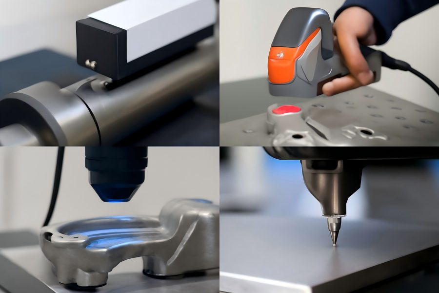
Forgings and castings’ surface roughness is measured using a variety of methods. These techniques fall into two general categories: touch and non-contact procedures.
Contact Methods
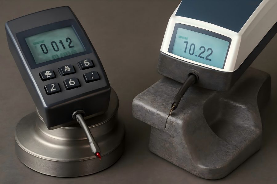
Stylus Profilometer: Because of its accuracy and ease of use, this technique is frequently employed. A diamond-tipped stylus moves along the surface, and the vertical displacement is recorded to assess the surface roughness. This method provides detailed data and is suitable for a wide range of materials.
| Pros | Cons |
| High accuracy and resolution | Surface preparation is critical for accurate readings |
| Suitable for rough and fine surfaces alike | Contact may affect soft materials or delicate surfaces |
Non-Contact Methods
Laser Scanning: This technique scans the part’s surface using a laser beam. The topography of the surface is measured using the data that is obtained from the light’s reflection off the surface. Laser scanning is effective for non-destructive testing, especially for delicate or soft surfaces.
| Pros | Cons |
| No physical contact, reducing the risk of damage | High initial cost and complexity |
| Faster measurements for large surfaces | Accuracy can be affected by surface reflectivity |
Optical Profilometry: Optical profilometry is similar to laser scanning but uses visible light and optical sensors to create a 3D surface map. High-resolution measurements can be obtained using this technique without coming into direct touch with the surface.
| Pros | Cons |
| High resolution | Surface reflectivity can affect accuracy |
| Suitable for complex geometries | Sensitive to lighting and environmental conditions |
Other Techniques
- Atomic Force Microscopy (AFM): AFM offers nanometer-scale resolution and is ideal for extremely fine surface measurements. It is very helpful for materials science research when describing surfaces.
- White Light Interferometry: This technique uses the interference of white light to create detailed surface maps at micrometer-scale precision, suitable for surfaces with intricate geometries.
| Pros | Cons |
| Extremely high resolution | Higher operational cost |
| Non-destructive and versatile for various materials | Complex setup and calibration |
Selection of Measurement Technique
The choice of surface roughness measurement method depends on several factors:
- Material Type: Soft materials or delicate surfaces may benefit from non-contact methods to prevent damage.
- Surface Finish: Extremely smooth surfaces may require the precision of non-contact methods like laser scanning or optical profilometry.
- Precision Requirements: For high-precision applications, methods like AFM or white light interferometry may be required.
Surface Roughness Standards and Parameters
Industry standards define how surface roughness should be measured and interpreted. ASME B46.1 and ISO 4287, for example, provide standards for measuring surface roughness.
Recommended Surface Roughness Values
- Automotive Industry: For components like engine parts and pistons, Ra values typically range from Ra 0.8 µm to Ra 3.2 µm.
- Aerospace Components: Turbine blades and critical aerospace components require higher precision, with roughness values around Ra 0.2 µm.
- Heavy Machinery: For larger parts like bearings, Ra values between Ra 3.2 µm to Ra 6.3 µm are common.
Table 1: Recommended Surface Roughness Values for Different Industries
| Industry | Recommended Ra Value (µm) | Description |
| Automotive | Ra 0.8 – Ra 3.2 | For engine parts and components requiring wear resistance |
| Aerospace | Ra 0.2 | For precision components like turbine blades and bearings |
| Heavy Machinery | Ra 3.2 – Ra 6.3 | For larger parts like bearings and other functional components |
Practical Applications of Surface Roughness Measurement
Surface roughness measurements have significant practical implications in various industries. In automotive manufacturing, for instance, the surface roughness of engine parts like pistons can affect the wear rate and overall engine efficiency. Smoother surfaces frequently have less friction, which over time improves fuel economy and lessens wear.
Similarly, in aerospace, turbine blades with smoother surfaces improve airflow and reduce the chances of premature wear or failure. These components are exposed to extreme conditions, so precise control of surface roughness is critical for operational safety and longevity.
Example: Bearings in Heavy Machinery
In the case of heavy machinery, the surface roughness of bearing surfaces plays a key role in the longevity and performance of the machine. By ensuring smooth finishes on bearing surfaces, friction is minimized, heat generation is reduced, and the lifespan of the bearings is extended.
Common Issues in Measuring Surface Roughness
There are several common issues that can impact the accuracy of surface roughness measurements:
- Surface Preparation: The cleanliness of the surface being measured is critical. Dust, oil, or other contaminants can distort readings, especially with contact-based methods like stylus profilometry.
- Environmental Conditions: Temperature and humidity can affect measurement, particularly for non-contact methods like optical profilometry or laser scanning. Keeping the surroundings under control might lessen these impacts.
- Measurement Errors: Inaccurate measurements may result from incorrect settings, calibration mistakes, or equipment failure. Maintaining consistent results requires routine calibration and upkeep.
Table 2: Common Measurement Errors and Solutions
| Common Error | Description | Solution |
| Surface Contaminants | Dust, oil, or other residues on the surface can distort measurements. | Make sure the surface is cleaned and prepared correctly. |
| Environmental Conditions | The precision of measurements can be impacted by changes in humidity and temperature. | Perform measurements in a controlled environment. |
| Improper Calibration | Incorrect equipment settings can cause inaccurate readings. | To guarantee precision, calibrate and maintain equipment on a regular basis. |
Case Studies
Case Study 1: Automotive Component
An automotive manufacturer used a stylus profilometer to measure the surface roughness of forged engine components. After measuring and optimizing the roughness, the manufacturer noted a significant improvement in the component’s performance, particularly in terms of wear resistance and friction.
Case Study 2: Aerospace Turbine Blades
Aerospace manufacturers employed optical profilometry to measure turbine blade surfaces. By optimizing the surface roughness to Ra 0.2 µm, they achieved enhanced airflow efficiency and improved durability, leading to longer component lifespans and better performance under extreme conditions.