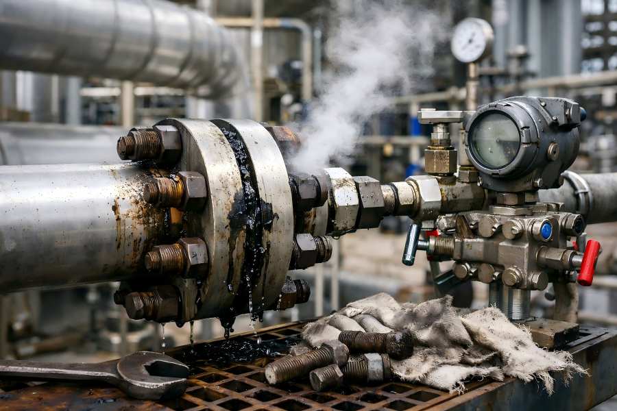
Orifice flanges are crucial components in industrial piping systems, enabling precise flow measurement and ensuring the safety and efficiency of high-pressure operations.
Despite their robust design, these flanges are vulnerable to various failures, which can cause leaks, downtime, and even catastrophic accidents. Understanding the causes of failure and implementing preventative measures is essential for engineers, maintenance teams, and facility managers.
Understanding Orifice Flanges
Orifice flanges hold an orifice plate to create a controlled restriction, generating differential pressure for accurate fluid flow measurement. They are used in oil, gas, petrochemical, power, water, and chemical industries.
Types of Orifice Flanges
- Orifice Weld Neck Flanges: These flanges have a long tapered hub, providing excellent alignment and strength. Ideal for high-pressure and high-temperature applications.
- Orifice Socket Weld Flanges: Installed by inserting the pipe into a socket and welding around the joint. Common in small-diameter, medium-pressure systems.
- Orifice Slip-On Flanges: Easy installation for low-pressure systems, sliding over the pipe and welded at both ends for secure stability.
- Orifice Lap Joint Flanges: Typically used with stub ends, allowing convenient disassembly for inspection or maintenance needs.
Common Causes of Orifice Flange Failures
Failures can occur for multiple reasons, often interrelated. Understanding these causes allows engineers to address problems proactively.
Improper Material Selection
One of the main reasons for flange failure is incorrect material selection. As an example:
- Using carbon steel in highly corrosive systems can result in rapid rusting, pitting, and eventual leaks.
- Using standard stainless steel grades in high-abrasion applications may lead to excessive wear.
Example: A chemical processing plant experienced rapid corrosion on carbon steel flanges exposed to chloride-laden fluids, leading to shutdowns and replacement costs exceeding $50,000.
Prevention: Evaluate fluid composition, operating temperature, pressure, and potential abrasives to determine the appropriate flange material. Consider high-performance alloys in extreme conditions.
Poor Installation Practices
Incorrect installation often leads to flange failure, even if the flange is high-quality. Common issues include:
- Misalignment: Causes uneven stress on the flange face and gasket, leading to leaks or flange warping.
- Over-tightening or under-tightening bolts: Over-tightening may deform the flange; under-tightening results in insufficient gasket compression.
- Skipping torque sequences: Uneven bolt tension can compromise seal integrity.
Example: In a refinery, improper installation of the orifice weld neck flange led to a high-pressure leak that forced unscheduled downtime and costly emergency maintenance.
Prevention: Train installation teams on torque specifications, alignment techniques, and recommended bolt patterns. Adhere to the manufacturer’s recommendations and use torque wrenches that have been calibrated.
Gasket Failures
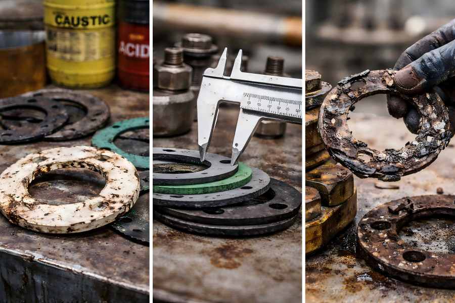
Gaskets seal the flange joint and prevent leaks. Common failure modes include:
- Material incompatibility: Certain gasket materials fail under specific chemicals, pressure, or temperature.
- Incorrect thickness or size: Poor fit causes uneven sealing surfaces and leaks.
- Aging: Gaskets lose elasticity over time.
Table: Common Gasket Issues and Impacts
| Issue | Impact | Prevention |
| Material incompatibility | Leakage, chemical attack | Use chemically compatible gasket |
| Incorrect thickness | Uneven compression | Follow manufacturer specifications |
| Aging or wear | Reduced sealing | Regular inspection and replacement |
| Improper installation | Damage, leakage | Correct alignment and torque |
Extended Tip: Gaskets should always be kept in a dry, regulated atmosphere. Avoid bending or folding gaskets during installation to prevent micro-cracks.
Mechanical Stress and Vibration
High-frequency vibrations from pumps, compressors, and turbulent flow can cause:
- Fatigue cracks in the flange body.
- Loosening of bolts, leading to leakage.
- Accelerated wear on flange faces and gaskets.
Example: A petrochemical plant experienced repeated fatigue cracks in weld neck flanges due to pulsating flow from centrifugal pumps. Installing vibration dampers and increasing inspection frequency mitigated further damage.
Prevention: Use vibration isolators, properly support piping, and avoid abrupt bends near flanges. Conduct regular vibration monitoring.
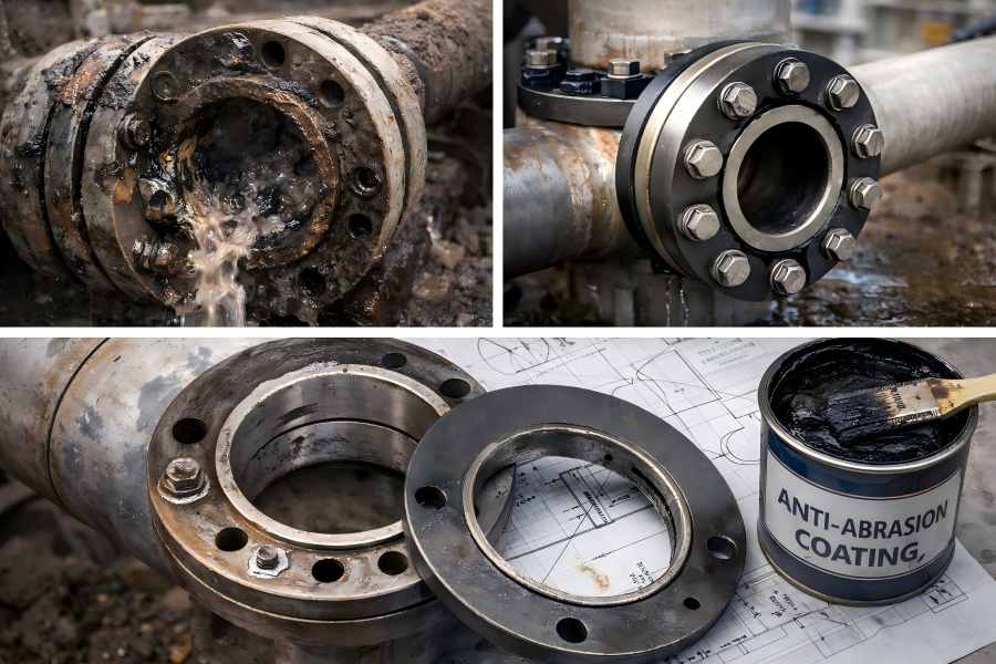
Corrosion and Environmental Factors
Environmental exposure accelerates flange deterioration:
- Chemical corrosion: Acidic or alkaline fluids attack the metal surface.
- Moisture and Humidity: Encourage rust formation and surface pitting.
- Temperature Extremes: Trigger thermal expansion and contraction, creating material stress.
- Galvanic Corrosion: Develops when two different metals are in direct contact.
Extended Prevention: Apply protective coatings, select corrosion-resistant alloys, or install sacrificial anodes in critical environments. Regularly inspect exposed flanges for rust, discoloration, or pitting.
Wear and Erosion
Flanges exposed to high-velocity fluids containing abrasive particles suffer:
- Surface erosion, thinning the flange wall.
- Gasket seat degradation, increasing leak potential.
Example: A slurry transport line in a mining operation eroded carbon steel flanges within a year, requiring replacement. Engineers switched to hardened alloy flanges and installed sacrificial wear liners, extending service life by threefold.
Prevention: Use wear-resistant alloys, protective coatings, and sacrificial liners in high-velocity areas. Implement flow velocity controls if possible.
Human Error
Beyond technical factors, human error contributes to many flange failures:
- Improper torque application.
- Neglecting inspection schedules.
- Incorrect gasket installation.
Prevention: Train maintenance personnel, implement checklist-driven inspections, and enforce quality control standards.
Warning Signs of Orifice Flange Failure
Preventing system damage requires early detection. Warning signs include
- Visible leaks or drips.
- Unusual noises or vibrations.
- Pressure fluctuations.
- Rust, pitting, or surface cracks.
- Deformed or misaligned flanges.
Tip: Installing pressure and vibration sensors can provide continuous monitoring, alerting engineers to potential failures before catastrophic events occur.
Prevention Strategies and Best Practices
Proper material selection, installation, upkeep, and monitoring are all part of prevention.
Appropriate Material Selection
- For corrosion resistance, use stainless steel.
- Alloy steel for high-pressure or high-temperature applications.
- Carbon steel with protective coatings for cost-sensitive systems.
- Consider abrasive media; choose hardened alloys for erosion resistance.
Proper Installation Techniques
- Check flange alignment and parallelism.
- Apply correct bolt torque in recommended sequences.
- Use thread lubricants when appropriate.
- Make sure the flange faces are clear of debris and clean.
Regular Inspection and Maintenance
- Visual examinations, ultrasonic thickness measurements, and non-destructive testing (NDT).
- Replace gaskets according to service intervals.
- Document all inspections for maintenance planning.
Table: Inspection Checklist for Orifice Flanges
| Inspection Item | Frequency | Action |
| Bolt torque | Every 3–6 months | Adjust to manufacturer specs |
| Flange alignment | Every 6 months | Correct misalignment |
| Gasket condition | Annually | Replace if worn or damaged |
| Surface corrosion | Quarterly | Clean and apply protection |
Controlling Mechanical Stress
- Vibration dampers or flexible connectors should be installed.
- Support pipes to lessen flange stress.
- Minimize abrupt directional changes near flanges.
Corrosion Protection Measures
- Apply industrial coatings, galvanization, or painting.
- Install sacrificial anodes where applicable.
- Monitor environmental conditions and perform preventive maintenance.
Operational Monitoring
- Use pressure sensors, flow meters, and vibration monitoring.
- Track deviations from normal operating conditions to detect early-stage failures.
- Schedule predictive maintenance using sensor data.
Case Studies
Case Study 1: Chemical Plant Flange Leak
Carbon steel flanges corroded in a chloride-rich environment, causing leakage. Replacement with stainless steel and proper gasket selection restored system reliability.
Case Study 2: Vibration-Induced Fatigue
Repeated pressure pulsations in a refinery led to weld neck flange cracks. Adding vibration dampers and implementing more frequent inspections prevented further failures.
Case Study 3: Erosion in Mining Slurry Systems
High-velocity sand-laden slurry caused erosion in carbon steel flanges. Switching to hardened alloy flanges with sacrificial liners extended service life by three times.