Casting is a foundational manufacturing process for producing metal parts with complex geometry in large volumes. Yet even experienced foundries frequently encounter defects that elevate scrap, rework, and cost. Recognizing the most frequent defects—and adopting targeted solutions—helps manufacturers boost yield, cut costs, and enhance product quality.
Casting Defects and Solutions Table
| Defect Type | Key Root Cause | Practical Solution |
| Porosity | Gas entrapment, turbulence, poor feed | Degas melt, improve venting & flow design |
| Shrinkage Cavities | Insufficient feeding, hot spots | Optimize risers & chills, uniform section design |
| Cold Shut | Poor fusion of flows, low fluidity | Adequate pour temp, smooth gating, reduce oxides |
| Misrun | Incomplete fill, early solidification | Increase fluidity, improve gating, pre-heat mould |
| Hot Tear / Crack | Thermal stress during solidification | Better geometry, collapsible mold, controlled cooling |
| Inclusions | Foreign particles, oxide films | Filter melt, reduce turbulence, clean melt & mold |
| Sand/Mould Surface Defects | Mould erosion, embedded sand | High quality sand, controlled velocity, coatings |
| Mold/Core Shift | Misalignment, movement of cores | Precise alignment, secure molds, support cores |
| Gas Defects | Trapped gases, moisture, poor venting | Dry molds/cores, degas melt, improve venting |
| Warpage/Distortion | Uneven cooling, internal stress | Uniform thickness, controlled cooling/support |
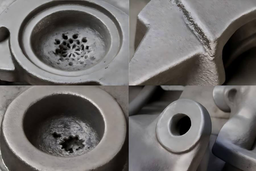
1. Porosity
Porosity refers to voids, bubbles or cavities within a casting’s metal structure. These voids can undermine structural strength, reduce fatigue resistance, compromise pressure integrity, and create leak paths or machining issues.
Causes:
- Gases dissolved in molten metal (for example hydrogen in aluminum or nitrogen in steel) that come out of solution during cooling.
- Entrapped air or gases due to inadequate venting of the mold or core, or due to turbulence during pouring.
- Oxide film folding or entrainment, which traps gas pockets beneath the solidified skin.
- Insufficient feeding of molten metal into contracting regions, leaving micro-voids as metal solidifies.
- Moisture or volatiles in the mold or core materials generating gases when contacted by molten metal.
Solutions:
- Degas the molten metal before pouring, using vacuum degassing, inert gas sparging or fluxing to reduce dissolved gas content.
- Ensure mold and core venting is effective—design proper vent channels, ensure permeability of sand or shell mold systems, minimize trapped air.
- Optimize pouring temperature and speed to maintain fluidity and minimize turbulence/air entrainment.
- Design gating and riser systems to provide sufficient feeding into the last-to-solidify zones so voids are properly compensated.
- Utilize low-moisture, low-volatile binder systems for cores and molds; ensure thorough drying/cure of molds to eliminate gas generation during pouring.
Commercial benefit:
Reducing porosity results in stronger castings, better machining yields (fewer internal defects causing tool breakage or scrap), improved leak-tight parts, and fewer field failures — all contributing to lower cost per part and stronger customer confidence.
2. Shrinkage Cavities and Voids
Metal that is molten contracts as it cools and solidifies. If the region still liquid cannot be fed by additional molten metal, cavities can form—either large visible voids or dispersed micro-shrinkage. These reduce structural integrity and may lead to brittle zones or failure under stress.
Causes:
- Inadequate riser/feeder positioning or sizing, causing insufficient metal feed to compensate contraction.
- Non-uniform section thickness (e.g., thick sections adjacent to thin ones) creating “hot spots” that solidify last, trapping shrinkage.
- Low pouring superheat or temperature causing early skin solidification and locked-in shrinkage.
- Constrained or inefficient solidification paths, meaning pockets of liquid metal are cut off from feed sources.
Solutions:
- Design risers/feeding systems that properly sustain metal to the end of solidification; locate them at the last solidifying zones and provide adequate volume.
- Apply chills (metal or ceramic inserts) or insulating sleeves to adjust cooling rates and encourage directional solidification toward the feeder.
- Aim for more uniform wall thickness in casting design; avoid large disparities between thin and thick sections.
- Use casting simulation during design to identify shrink-risk zones and optimize gating, risers and cooling layout ahead of production.
- Maintain proper melt temperature and fluidity so metal can flow and fill fully until complete solidification is achieved.
Commercial benefit:
By eliminating shrinkage cavities, manufacturers reduce scrap risk, improve internal structural soundness (which is important for fatigue, pressure, load-bearing castings) and avoid costly repairs or warranty claims. Better yields and stronger parts translate to more robust profitability.
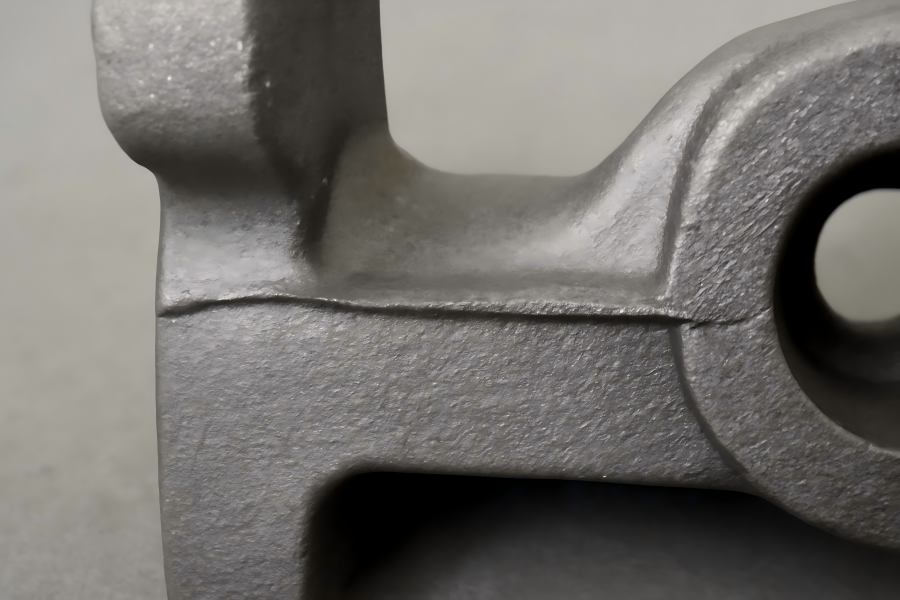
3. Cold Shut (or Cold Lap)
A cold shut occurs when two frontiers of molten metal meet but fail to merge properly, leaving a seam, line, or weak plane in the casting. This defect can reduce mechanical strength, create a visible crack or seam, or serve as a crack origin.
Causes:
- Low metal fluidity or inadequate superheat, meaning the metal solidifies too quickly before full fusion.
- Slow or interrupted pouring so that an earlier flow partly solidifies before another stream meets it.
- Poor gating or runner design that causes the metal to change direction sharply or lose momentum, increasing oxide film formation and reducing weld of the flows.
- The flows’ metal surfaces are coated with oxides, which inhibit complete metallurgical bonding.
Solutions:
Select appropriate pouring temperature and maintain melt fluidity for the specific alloy; ensure the metal arrives in the cavity with proper momentum.
- Optimize gating/runner systems to create smooth, rapid, and continuous filling of the mold, reducing dead zones or slow flow fronts.
- Keep the metal stream clean and free of excess oxide films — employ good melt practices, proper fluxing, skimming and degassing as needed.
- Minimize the distance from gate to cavity, direct flow where possible, avoid abrupt changes that cause turbulence or film formation.
Commercial benefit:
Preventing cold shuts helps avoid weak planes or cracks that may later propagate or fail under load. This leads to fewer rejects, better structural parts (especially for safety-critical components), fewer returns, and higher customer satisfaction.
4. Misrun (Incomplete Filling)
A misrun occurs when molten metal fails to fill the mold cavity entirely before it solidifies, leaving unfilled sections, jagged or incomplete areas. The result is a part that is incomplete, weaker and often unusable.
Causes:
- Poor metal fluidity (low pouring temperature or low alloy superheat) so the metal solidifies early.
- Inadequate gating/runner/sprue design reducing flow rate or causing early cooling of the metal before full fill.
- Cold mold, mold surfaces or core leading to premature cooling of molten metal before it reaches all regions.
- Insufficient venting or trapped air impeding metal flow, or high resistance flow paths that slow fill.
Solutions:
- Increase pouring temperature (within alloy limits) to improve fluidity and maintain fill rate.
- Re-design gating/runner/sprue to ensure adequate cross-section, minimal resistance, smooth transitions and efficient flow to all mold sections.
- Pre-heat mold and cores where necessary to prevent chilling of the metal.
- Incorporate proper vents to allow air to escape, lowering flow resistance and ensuring complete filling before solidification sets in.
Commercial benefit:
Correcting misruns improves part completeness, structural integrity and reduces scrap. More complete castings mean higher first-pass yield, fewer machining or finishing issues, fewer delays and better cost control.
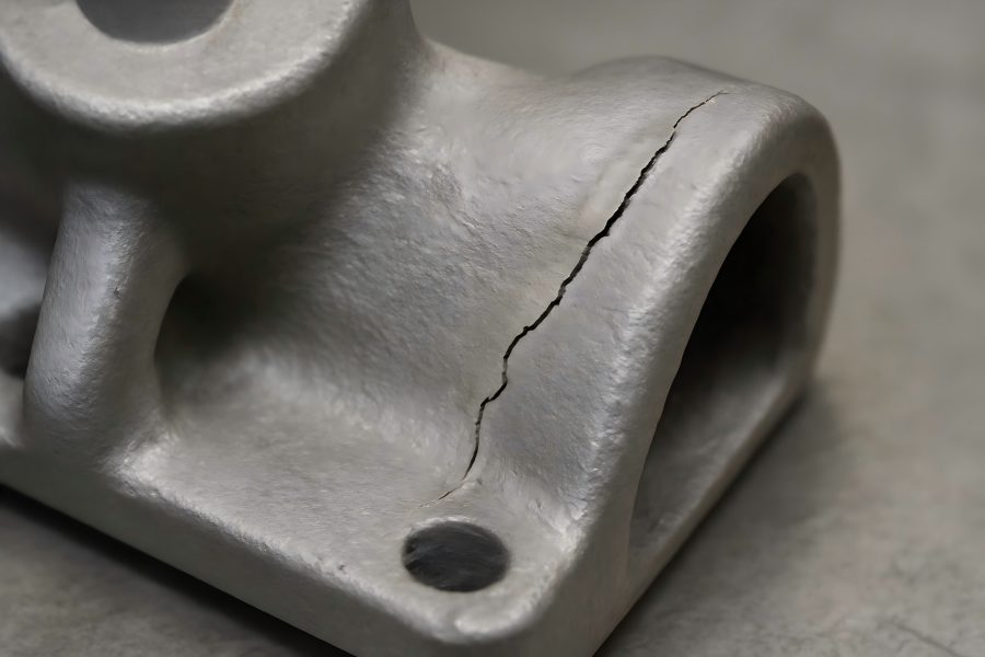
5. Hot Tear / Hot Crack
Hot tears or hot cracks develop when the casting is still in the phase of solidification or shortly thereafter when it cannot sustain internally generated tensile stresses caused by contraction. These cracks often appear in thin junctions, corners or where geometry restricts movement.
Causes:
- Stress concentrations arising from abrupt changes in section thickness, sharp corners or poor geometry causing the metal to contract and tear under tensile load.
- Mold or core materials that do not yield or collapse sufficiently during solidification, restraining the casting’s natural contraction.
- Alloys with wide solidification ranges (long freezing intervals) which remain weak for longer, increasing susceptibility.
- Rapid cooling or large thermal gradients causing different parts of the casting to shrink at different rates, generating internal stress.
Solutions:
- Design castings with gradual transitions in section thickness, use fillets instead of sharp corners, and avoid abrupt geometry changes that trap stress.
- Use mold and core materials that allow some movement or collapse during solidification, reducing mechanical restraint on the casting.
- Control cooling rates—use chills or insulation to balance cooling across the casting and avoid extreme gradients.
- Choose alloys with narrower freezing ranges where possible, or adjust alloying to strengthen the final solidification phase if permissible.
Commercial benefit:
By minimizing hot tears, parts made are structurally sound, have fewer hidden or early-service cracks, fewer rejects and reduced liability. This improves yield, reliability in service and protects brand reputation.
6. Inclusions (Non-Metallic)
Inclusions are foreign materials embedded within the casting metal matrix—examples include oxide films, slag, sand grains, refractory fragments or other non-metallic impurity. They degrade mechanical performance, surface finish and appearance.
Causes:
- Poor filtration of molten metal before it enters the mold; slag, dross or oxide films remain in the flow.
- Turbulence in flow causing oxide films or slag to fold in (entrainment) and become trapped in the casting.
- Degraded furnace or ladle linings, contaminated charge materials or refractory erosion dropping particles into the melt.
- Mould or core sand grains, binder fragments or coatings breaking into the molten metal due to erosion or weak sand strength.
Solutions:
- Install and maintain appropriate filters (e.g., ceramic foam filters, mesh, gating traps) to remove inclusions before the metal enters the mold.
- Reduce turbulence and optimize gating/runner design for smooth flow and minimal oxide film formation or entrapment.
- Maintain furnace and ladle quality, ensure regular cleaning, lining inspections, proper charge preparation and slag removal.
- Strengthen mold/core materials, apply refractory coatings as needed, control pouring velocity so mold erosion and sand drop are minimized.
Commercial benefit:
Fewer inclusions mean better fatigue strength, improved machinability, less tool wear, fewer cosmetic defects and higher customer satisfaction. The reduced scrap and finishing cost also enhance profitability.
7. Sand / Mould Surface Defects (Cuts, Washes, Sand Inclusions)
In sand-casting, one of the common defect categories involves the mold itself: inadequate compaction, erosion by flowing metal, sand grains embedded in the casting, or molten metal penetrating between sand grains. These defects affect surface finish and can lead to embedded sand in the final product.
Causes:
- Weak or improperly compacted sand with insufficient binder, excessive moisture, or reduced density leading to mold breakdown.
- Excessive pouring velocity causing erosion of mold surface, sand falling into the cavity or rough surfaces due to wash.
- Poor quality coatings or washes on the mold surface, inadequate protection leading to sand penetration by molten metal.
- High mold surface temperatures or molten metal penetrating between sand grains when molds are improperly prepared or sand is coarse.
Solutions:
- Use high-quality moulding sand with proper binder ratios, control moisture and compaction, and ensure consistent permeability and strength.
- Optimize pouring velocity, gating design to minimize erosive metal flow on mold surfaces; reduce metal turbulence near walls.
- Apply appropriate refractory coatings or wash layers on mold surfaces to prevent penetration and protect integrity.
- Monitor moulding parameters (ramming pressure, sand strength, hardness, permeability) and maintain strict mold prep standards.
Commercial benefit:
Reduced surface defects lead to less cleaning or finishing work, fewer visual or embedded sand defects, improved surface quality (important for visible parts), lower tool wear in post-machining and improved customer satisfaction — all lowering total cost of production.
8. Mold Shift / Core Shift (Mismatch)
Mold or core shift refers to misalignment between mold halves (cope and drag) or movement of cores during the pouring process, resulting in mismatched parting surfaces, steps or dimensional irregularities. This defect disrupts dimensional accuracy and repeatability.
Causes:
- Poor alignment of mold halves or worn locating pins causing displacement during pouring or metal flow.
- Inadequate clamping or securing of molds; vibration or hydraulic pressure from pouring causing movement.
- Buoyancy or flow forces acting on cores causing them to shift downward, laterally or vertically in the cavity during filling.
- Insufficient support for cores (lack of chaplets, inadequate seating) allowing them to move when molten metal pressure hits them.
Solutions:
- Use robust locating and locking systems for mold halves; inspect and maintain aligning pins and clamp fixtures regularly.
- Secure the mold firmly before pouring, isolate from vibrations or pouring‐induced forces, ensure minimal movement during fill.
- Properly support cores—use chaplets, anchors or supports designed for the casting’s metal pressure and buoyancy forces.
- Check molds and cores for seating, register features, alignment before production runs; incorporate checks for shift or mismatch in quality control.
Commercial benefit:
Reducing mold or core shift improves dimensional accuracy, lowers machining allowances (less offset added), reduces scrap or rework due to misalignment, improves first‐pass yield and enhances overall production efficiency.
9. Gas Defects (Blowholes, Pinholes)
Gas defects occur when gases are trapped in the metal or mould during solidification. Blowholes are larger voids visible near or at the surface; pinholes are smaller, near‐surface or subsurface gas pockets. These compromise surface integrity, function and appearance.
Causes:
- Moisture, volatiles or binder decomposition in molds/cores generating gas when in contact with molten metal.
- Poor venting of molds/cores causing trapped gas which then enters the molten metal and solidifies as voids.
- Turbulence during pouring causing air/gas entrapment in the metal stream.
- High levels of dissolved gases in molten metal (for instance hydrogen in aluminium) releasing during cooling and forming cavities.
Solutions:
- Ensure molds and cores are properly dried and any binder volatiles minimized; control moisture in sand or shell systems.
- Improve mold and core venting; provide dedicated vent channels, bleed holes, high‐permeability materials to permit gas escape.
- Optimize pouring practices to reduce turbulence and entrainment of gas; ensure smooth flow, adequate velocity without excessive turbulence.
- Degas the molten metal or reduce dissolved gas content before pouring; monitor melt gas levels and treat if necessary.
Commercial benefit:
By mitigating gas defects, manufacturers improve surface finish, avoid leak paths (critical for pressure systems), reduce pinhole or blowhole induced failures in service, decrease rework and boost part quality and reliability.
10. Warpage and Distortion
Warpage or distortion refers to a casting bending, twisting or otherwise deforming during or after solidification, so that it no longer meets the dimensional, tolerance or design-fit requirements. Though not always a “visible defect” like a crack, warped parts often fail fit-up or require expensive straightening or re‐machining.
Causes:
- Uneven wall thickness or geometry causing different regions to cool, contract or support differently, leading to internal stresses and distortion.
- Inadequate support or restraint during cooling, allowing the part to sag or deform under its own weight or due to thermal gradients.
- Mold or core layout that rigidly constrains part of the casting while other regions shrink, causing warp due to differential contraction.
- Rapid cooling in one portion while adjacent portions remain hot, creating thermal gradients and internal residual stress.
Solutions:
- Design parts with uniform wall thickness where possible, avoid abrupt transitions in section thickness that encourage distortion.
- Provide proper fixturing/support during solidification and cooling; consider using fixtures that allow controlled contraction or avoid sagging.
- Use chills, insulating sleeves or controlled cooling systems to moderate cooling rates and reduce thermal gradients.
- During design phase, evaluate warpage risk zones and include features or allowances for straightening or finishing if complete prevention isn’t feasible.
Commercial benefit:
Minimizing warpage ensures dimensionally accurate parts that fit properly into assemblies without extra machining or corrective operations. This reduces cost, shortens cycle times, improves throughput and enhances customer satisfaction and part reliability.
Building a Robust Casting Quality Ecosystem
Understanding defect types and solutions is critical—but the real value to manufacturers comes when they build a process framework around defect prevention, monitoring and continuous improvement. Below are key strategic practices.
Non-Destructive Testing (NDT) & Inspection
Implement regular inspections using visual checks, dye penetrant methods, ultrasonic testing, X-ray or radiography to detect internal or surface defects early. This allows you to catch and correct issues before significant downstream cost is incurred.
Process Monitoring & Data Capture
Monitor critical process parameters: melt temperature, metal composition, mold and core temperatures, sand moisture, gating dimensions, venting performance, pouring speed and more. Logging data helps identify trends and root causes rather than reacting to defects after they occur.
Defect Tracking & Root Cause Analysis
Maintain a defect log capturing defect type, frequency, location on the part, production conditions at time of defect and cost impact. Use this data to identify recurring issues, drive corrective action (e.g., change gating design, alter process settings, train staff), and monitor improvement over time.
Design for Manufacturability (DFM) & Castability Review
Involve casting engineers early in part design to review wall thickness, gating/risers, moldability, ventilation, cooling path and solidification behavior. Employ casting simulation software to predict flow, cooling and shrinkage behavior, identify risk zones, and adjust design before tooling investment.
Workforce Training & Operator Empowerment
Ensure molders, core-makers, pour operators, finishing staff and quality personnel are trained on defects, causes and identification. Empower them to flag early warning signs (such as unexpected mold behavior, abnormal pouring conditions, excessive turbulence) so corrective actions can be taken proactively.
Maintenance & Tooling Integrity
Many defects stem from worn tooling, compromised mold alignment, eroded ladles, degraded filter systems or mis-clamped molds. Regularly inspect and maintain tooling, alignment pins, ladle linings, filter systems, gating fixtures and mold/clamp rigging to keep the process tight and predictable.
Continual Process Review & Technology Upgrades
Casting processes and materials keep evolving (improved mold materials, new coatings, advanced degassing systems, digital monitoring, simulation). Investing in the right upgrades—when ROI is clear—can lead to tangible defect reduction, improved throughput, better yield and lower cost per part.
Economic and Competitive Implications
Casting defects carry far more than just technical cost—they impose scrap, rework, downstream machining issues, warranty returns, delays, customer dissatisfaction and market risk. In competitive sectors such as automotive, aerospace, energy or heavy machinery, defect-free casting becomes a strategic differentiator.
Manufacturers taking a structured, proactive approach typically achieve yield improvements in the range of 10-25 % (or more, when starting from high defect baselines). Fewer defects reduce cost per part, shorten lead-times, improve tool life, reduce finishing and inspection effort, and ultimately strengthen market positioning. Improved casting quality also elevates downstream performance (machining, assembly, service life), which enhances reputation, repeat business and profitability.