Steel forging stands at the core of modern heavy-industry manufacturing. From automotive axles and turbine shafts to construction machinery and rail couplings, forged steel components define the strength, safety, and longevity of countless mechanical systems. However, even with advanced presses, precise dies, and strict process control, defects can still occur—undermining both performance and profitability.
Understanding the root causes of these defects and implementing practical, shop-floor solutions is vital for every manufacturer aiming to achieve consistent quality and long-term reliability.
Steel Forging Defects and Solutions Table
| Defect Type | Primary Cause | Practical Solution |
| Cracks (Hot/Cold) | Thermal stress, hydrogen, improper cooling | Uniform heating, preheat dies, stress relief |
| Laps/Folds | Sharp corners, low temperature, poor flow | Smooth die design, proper lubrication, preheating |
| Underfill | Low tonnage, cold dies, poor billet design | Correct press load, optimal temperature, preform correction |
| Scale & Decarburization | Oxidizing atmosphere, long soak time | Protective coating, shorter heating, shot blasting |
| Shrinkage Cavities | Nonuniform cooling, insufficient deformation | Heavy reduction, directional solidification, UT inspection |
| Grain Flow Discontinuity | Poor preform or die design | Simulated flow analysis, proper alignment |
| Inclusions | Contaminated steel, slag entrapment | Clean melts, degassing, ultrasonic inspection |
| Warpage | Uneven cooling, residual stress | Controlled cooling, stress relief annealing |
| Excess Flash | Oversized billet, poor trimming | Accurate volume control, sharp tools, trimming inspection |
| Improper Microstructure | Incorrect heat treatment | Controlled cycles, temperature monitoring, grain refinement |
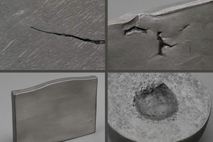
1. Cracks (Hot and Cold Cracking)
Cracking is among the most serious forging defects. It occurs when internal or external stresses exceed the material’s ductility during or after deformation. Hot cracks develop during forging, while cold cracks typically form during cooling or subsequent treatments.
Causes:
- Excessive stress during deformation or die separation.
- Overheating or underheating, creating temperature gradients within the billet.
- Hydrogen embrittlement due to moisture or contamination in steel.
- Improper cooling rates or inadequate preheating of large billets.
Solutions:
- Maintain uniform forging temperatures within the recommended range for the steel grade.
- Preheat large billets and dies evenly to avoid sharp temperature drops.
- Control hydrogen by keeping the atmosphere dry and the steel clean.
- Apply controlled cooling and post-forging stress-relief heat treatment.
- Before you complete, do non-destructive testing (NDT) to find any concealed cracks.
Impact:
Cracks can render heavy-duty parts like shafts or gears unsafe for use. Preventing them not only reduces scrap but also safeguards your reputation for reliability in critical industries.
2. Laps and Folds
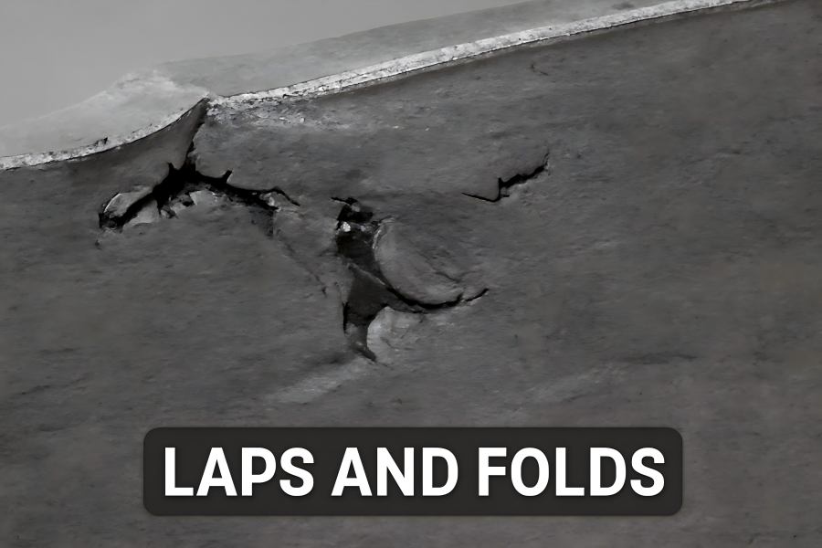
Laps or folds form when the material surface folds over itself during forging and fails to bond internally. These flaws cause premature fatigue failures by acting as stress concentrators.
Causes:
- Poor die design with sharp corners or abrupt directional changes.
- Insufficient forging temperature leading to low plasticity.
- Inadequate forging pressure or lubrication, resulting in uneven flow.
- Excessive scale on billet surfaces causing flow disruption.
Solutions:
- Redesign dies to promote smooth material flow and rounded transitions.
- Ensure proper billet heating and consistent temperature across the entire section.
- Apply effective die lubrication to minimize friction and folding.
- Descale billets before forging using shot blasting or chemical cleaning.
- Inspect forgings with surface testing methods to identify early-stage laps.
Impact:
Eliminating laps and folds ensures superior fatigue life and aesthetic surface finish—critical for visible or high-stress components like crankshafts, couplings, and drive axles.
3. Underfill (Incomplete Die Filling)
Underfill occurs when molten or solid metal fails to fill the die cavity completely. The result is missing sections, reduced dimensions, or insufficient wall thickness—leading to part rejection or costly rework.
Causes:
- Insufficient forging pressure or press tonnage.
- Low forging temperature, reducing metal flowability.
- Inaccurate billet size or improper preform design.
- Cold dies absorbing heat from the billet.
Solutions:
- Confirm press capacity matches the required load for full die fill.
- Maintain billet and die temperatures within the target range.
- Adjust billet volume and preform shape to promote complete filling.
- Apply proper lubrication and die heating before each forging cycle.
- Use flow simulation software to verify filling behavior.
Impact:
Underfill directly reduces usable material and compromises strength in critical regions. Consistent billet temperature and proper die design are key to eliminating this costly defect.
4. Scale and Surface Decarburization
Scale refers to iron oxides forming on the billet surface during heating. Decarburization is the loss of carbon at the surface layer due to oxidation. Both lead to poor surface quality and reduced hardness or wear resistance.
Causes:
- Extended heating or exposure to an oxidizing atmosphere.
- Excessive furnace time or poor temperature control.
- Contaminated fuel or oxidizing furnace gas composition.
- Lack of protective coatings or neutral atmospheres during heating.
Solutions:
- Reduce the soaking time and make sure the warmth is distributed evenly.
- Use controlled or neutral furnace atmospheres to prevent oxidation.
- Apply anti-scale coatings to billets before heating.
- Immediately clean forged parts by shot blasting or pickling after forging.
- Perform surface hardness or carbon-depth testing to ensure compliance.
Impact:
Minimizing scale and decarburization lowers machining allowances, improves fatigue resistance, and enhances surface finish—essential for high-load contact parts.
5. Shrinkage Cavities and Internal Voids
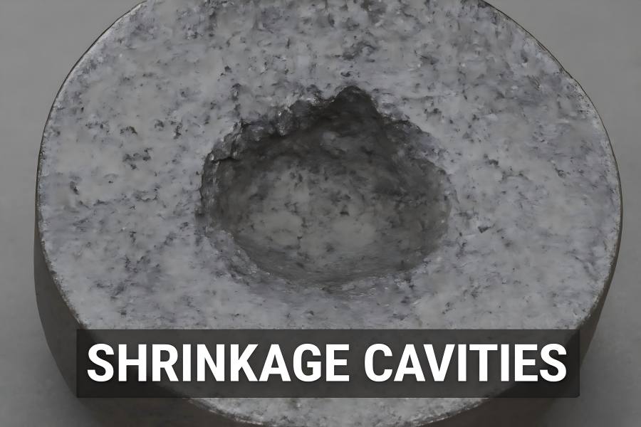
Shrinkage cavities form inside large forgings when molten metal or hot zones cool unevenly. The central area contracts, leaving cavities or micro-voids that weaken the part’s integrity.
Causes:
- Large cross-sections cooling too slowly at the core.
- Inadequate deformation to close porosity from the ingot stage.
- Poor billet quality or segregation within the raw material.
- Non-uniform cooling after forging or improper heat treatment.
Solutions:
- Use billets with verified internal soundness through ultrasonic inspection.
- Apply sufficient deformation (reduction ratio ≥ 3:1) during forging to eliminate voids.
- Employ directional solidification and preform design that promotes internal flow closure.
- Cool uniformly and stress-relieve large forgings to prevent shrinkage zones.
- Conduct UT scans or macro-etch inspections before machining.
Impact:
Internal voids can cause sudden fracture in service. Preventing them ensures reliable load-bearing capacity in turbines, press frames, and heavy-duty shafts.
6. Grain Flow Discontinuity
Forging aligns the grains along the shape of the component, giving superior strength. If the flow lines are disrupted, intersected, or misoriented, the component loses directional toughness.
Causes:
- Improper preform design leading to abrupt redirection of metal flow.
- Incorrect die geometry interrupting uniform deformation.
- Uneven billet temperature or off-center loading.
- Incomplete forging reduction or premature finishing.
Solutions:
- Design preforms and dies to ensure natural flow around corners and fillets.
- Use simulations to visualize grain flow and optimize deformation paths.
- Maintain consistent billet alignment and forging temperature.
- Apply adequate deformation during each stage to achieve continuous flow.
- Verify flow orientation by macro-etch testing on sample parts.
Impact:
Uniform grain flow enhances fatigue resistance and fracture toughness—especially vital in powertrain and structural applications.
7. Inclusion and Impurity Entrapment
Inclusions are non-metallic particles such as slag, oxides, or refractory debris trapped inside the metal matrix. These act as stress raisers and initiate cracks under cyclic loading.
Causes:
- Contaminated raw steel or improper melt refining.
- Excessive furnace slag carried into billets.
- Oxidation during reheating or metal flow turbulence.
- Inadequate filtration of molten steel before casting.
Solutions:
- Source high-purity billets and ensure inclusion control during steelmaking.
- Deslag and degas melts before solidification.
- Maintain clean furnace conditions and controlled heating environments.
- Use billet inspection and ultrasonic testing to detect subsurface inclusions.
- Implement filtration and controlled flow paths during reheating and forging.
Impact:
Reducing inclusions increases toughness and fatigue life, directly improving product consistency and reducing customer returns.
8. Warpage and Distortion
Distortion occurs when different parts of a forging cool or contract at varying rates. This leads to twisting, bending, or misalignment that affects machining accuracy and assembly fit.
Causes:
- Varying rates of cooling for thin and thick portions.
- Residual stresses from nonuniform deformation.
- Rapid quenching without sufficient pre-cooling.
- Poor fixture support during heat treatment.
Solutions:
- Design forgings with more uniform wall thickness.
- Control cooling rate using air fans, furnaces, or controlled media.
- Incorporate stress-relief annealing after forging.
- Use fixtures to support parts during heat treatment and prevent bending.
- Inspect dimensions immediately after cooling to detect early distortion.
Impact:
Preventing warpage ensures dimensional accuracy, lowers machining allowances, and eliminates costly rework for large steel components.
9. Excessive Flash or Trimming Defects
Flash forms when excess material is squeezed out between dies during forging. Excessive flash or poor trimming can waste material, increase machining effort, or leave sharp burrs on finished parts.
Causes:
- Oversized billets producing too much excess metal.
- Excessive die clearance or poor alignment.
- Over-pressing or incorrect stroke length.
- Dull trimming tools or misaligned trimming dies.
Solutions:
- Calculate billet volume accurately for each part design.
- Adjust die closure and flash land dimensions for optimal flow.
- Maintain trimming tools and ensure sharp edges for clean cuts.
- Use mechanical or laser trimming to reduce burrs.
- Regularly inspect flash thickness and trimming accuracy.
Impact:
Effective flash control improves efficiency, reduces waste, and minimizes post-processing costs—a direct productivity gain for high-volume forging lines.
10. Improper Microstructure or Heat-Treatment Response
Even when shape and dimensions are correct, microstructural defects can drastically reduce mechanical properties. Coarse grains, unrefined carbides, or retained austenite reduce toughness and fatigue life.
Causes:
- Incorrect forging temperature leading to incomplete recrystallization.
- Overheating and grain coarsening.
- Nonuniform cooling or improper quenching.
- Deviations in heat-treatment cycle (temperature, time, or medium).
Solutions:
- Strictly monitor temperature during forging and finishing passes.
- Apply intermediate normalizing steps to refine grains.
- Use controlled quenching and tempering suited to the steel grade.
- Validate heat-treatment uniformity using hardness and microstructure tests.
- Train operators on correct furnace loading and cycle adherence.
Impact:
Achieving a fine, uniform microstructure ensures each forged component meets or exceeds the strength, ductility, and toughness required for demanding service conditions.
Building Quality into the Forging Process
Preventing defects is not just about correction—it’s about establishing a culture of process control and continuous improvement. The following principles help ensure long-term consistency and customer confidence:
Material Integrity
Always begin with certified, clean steel. Ensure all incoming billets or ingots pass ultrasonic and chemical inspections. For large forgings, select material with low segregation and proven mechanical uniformity.
Process Monitoring
Install temperature sensors and digital monitoring systems on furnaces and presses. Record die temperature, billet core temperature, and press stroke data for traceability.
Die and Tooling Management
Regularly inspect dies for wear, cracking, or dimensional drift. Establish a preventive maintenance schedule and refurbish tools before quality deviations occur.
Non-Destructive Testing (NDT)
Employ NDT techniques like ultrasonic, magnetic-particle, and radiographic testing to identify internal defects before machining. Routine sampling reduces the risk of shipping defective parts.
Simulation and Predictive Control
Modern forging simulation software can model metal flow, temperature gradients, and defect risks before production begins. Using predictive analytics allows faster process optimization and reduced trial costs.
Heat Treatment Validation
Heat treatment determines the final properties of forged steel. Use precise furnace controls, calibrated thermocouples, and regular hardness testing to ensure every batch meets specifications.
Training and Continuous Improvement
When it comes to flaws, your operators are your first line of defense. Continuous education on process variables, defect detection, and equipment care ensures consistent results shift after shift.