
A forged disc becomes an orderable industrial component only when its blank dimensions are connected to the finished drawing and the planned manufacturing sequence. Diameter and thickness describe the starting envelope, but they do not explain where machining stock is needed, which face establishes location, or when bores and hole patterns must be completed. Buyers should define both the material they receive and the finished features that must fit inside it.
The same circular forging can be intended for a stationary cover, a mounting component, a drilled tube sheet, or a rotating part. These applications create different requirements for material, references, inspection, and finishing. This guide follows the transition from a forged blank to a controlled finished shape, with particular attention to the information that purchasing and manufacturing teams need to share.
Separate the Blank Drawing from the Finished-Part Drawing
State the manufacturing stage being purchased
An as-forged disc, a rough-turned disc, and a fully machined disc are different deliverables. Each has a different acceptance point. A supplier should not have to infer that point from an illustration of the finished assembly.
An as-forged delivery may retain scale, draft, and production-related shape variation within the agreed limits. A rough-machined delivery may provide cleaner surfaces and preliminary references while retaining stock for later work. A finished part must meet the features and condition assigned to final acceptance.
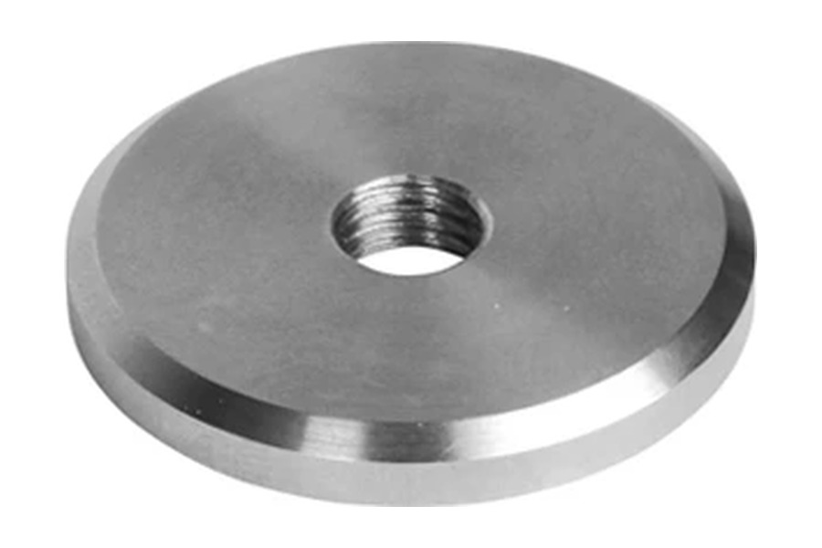
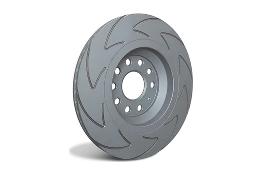
Boberry’s custom forged discs include flat, slotted, and tube-sheet forms. Those product descriptions help identify the family, but the approved drawing must establish which operations are included in a particular order.
Show which dimensions apply at receipt
Where possible, issue a blank drawing that is clearly linked to the finished drawing revision. Identify which features are controlled at receipt and which are supplied for reference only. This keeps a forging tolerance from being confused with a finished machining tolerance.
A combined drawing can work if it distinguishes the two states unambiguously. The important point is that receiving inspection, the forging supplier, and the machining team all use the same acceptance definition.
Record who is responsible for completing the next stage. If the buyer intends to drill or finish the component after delivery, that work should appear in the scope rather than remain an informal assumption.
| Drawing item | Blank-stage question | Finished-stage question |
| Outside diameter | Is sufficient stock available around the required axis? | Does the final diameter meet size and geometry requirements? |
| Thickness | Can both faces be cleaned up without losing required material? | Are final thickness and face relationships correct? |
| Central opening | Is the opening absent, preliminary, or ready for finishing? | Does the bore meet its fit and alignment requirements? |
| Hole pattern | Are holes included at this stage? | Are location, size, depth, and orientation verified? |
| Material condition | Is the workpiece suitable for the next operation? | Does the completed part meet its specified condition? |
Map the Finished Features Before Choosing Blank Dimensions
Identify functional and nonfunctional surfaces
Start with the surfaces that locate, support, seal, rotate, or connect to other components. These features determine where accuracy matters. A peripheral surface that only provides clearance may need a different requirement from a bore that locates the disc on a shaft.
Mark surfaces that remain as-forged and those that require machining. If surface appearance matters for handling or assembly, describe it separately from dimensional accuracy. A visually smooth surface is not proof of flatness, alignment, or material integrity.
Do not assign the same finish or tolerance to every surface solely for drawing convenience. Clear differentiation helps the manufacturer direct attention to the interfaces that control performance.
Establish an axis and locating face
A disc is geometrically simple only until its features must align with an assembly. A central bore may define the operating axis, while one face establishes axial position. Alternatively, a bolt pattern or another feature may control location.
Identify the locating features and their order of precedence directly on the controlled drawing. Measuring an outside diameter from one setup and a hole pattern from another can conceal a relationship that matters in service. A common reference structure connects those measurements.
The broader practice of geometric dimensioning and tolerancing provides a way to communicate relationships beyond individual sizes. Use the agreed drawing convention consistently and avoid adding unfamiliar symbols without defining how they will be inspected.
Preserve access for manufacturing
Deep recesses, narrow slots, and closely spaced holes can affect tool reach, support, and inspection. Discuss these features while the blank envelope is still being reviewed.
Temporary stock or workholding features may be needed to complete the component. If they change the purchased envelope, document them. Identify whether they remain at delivery or are removed before final acceptance.
The finished shape should fit inside the actual permissible blank, including the least favorable combination of accepted dimensions and shape variation. A nominal drawing overlay alone does not demonstrate that every accepted blank will clean up.
Allocate Machining Stock to Individual Surfaces
Distinguish allowance from tolerance
Machining allowance is material intentionally left for removal. A tolerance defines permitted variation around a specified dimension. Combining these two ideas can produce a blank that is nominally large enough but lacks stock at its accepted lower limit.
For an outside diameter, radial stock is half the difference between blank diameter and finished diameter, assuming aligned circular geometry. For face machining, total thickness stock must be divided between the two faces according to the planned setup.
If a preliminary bore is present, its stock works in the opposite direction: the opening must remain small enough for the required enlargement. An oversized opening remains a problem even when ample machining stock is available around the outer rim.
Use numerical examples only as geometry checks
Consider a hypothetical flat disc with a finished diameter of 400 mm and a finished thickness of 60 mm. If a process planner chooses 3 mm radial stock and 2 mm on each face, the nominal geometric envelope would be 406 mm in diameter and 64 mm thick.
These values illustrate the arithmetic only. They are not recommended forging allowances. Production requirements must also consider the actual forging tolerance, surface condition, distortion, reference selection, and machining method.
The example becomes incomplete if the blank can arrive below those nominal dimensions or with shape variation that reduces local stock. Review the permissible envelope, not just its center values.
Avoid using excess stock to conceal uncertainty
More material can provide flexibility, but it also changes handling, machining time, and the way the workpiece responds as stock is removed. A larger blank is not automatically a better blank.
Agree the minimum stock needed for reliable cleanup and the maximum envelope that the machining equipment can accept. Confirm chuck capacity, support, lifting arrangements, and tool access before finalizing dimensions.
When a blank is intended for several finished variants, check each variant against the common envelope. Document which features are shared and which require different machining references or retained material.
Plan Faces, Bores, and Hole Patterns as Related Features
Face machining establishes more than thickness
Two face measurements may confirm an overall thickness without fully describing face form or their relationship. Where a disc seats against another component, define the relevant flatness, parallelism, or orientation requirements.
The machining sequence should establish a suitable reference face before later operations depend on it. If material treatment occurs between operations, allow for reassessment of that reference afterward.
Discuss support during face machining. A compliant workpiece can be held flat under clamping and move after release. The inspection condition should represent the requirement stated on the drawing rather than merely reproduce the clamped machining setup.
Bores and recesses need a defined stage
A disc can be supplied solid, with a preliminary opening, or with a finished bore. These choices affect material use and the downstream process. State whether the opening is intended for workholding, access, or final assembly.
For stepped bores and recesses, identify depths from the appropriate face. Define corner geometry where it affects mating parts or tool access. A sharp internal corner shown schematically should not be left for the supplier to interpret as either functional or incidental.
If the bore establishes the rotation axis, coordinate its completion with the surfaces inspected relative to it. Measuring runout from a temporary feature may not represent the finished assembly.
Hole patterns require position and orientation
A drilling request should include more than hole count and diameter. Establish the pattern’s relationship to the axis, face, slots, or other features. Where angular orientation matters, identify the clocking reference.
For through holes, blind holes, threaded holes, and counterbores, define depth and entrance or exit requirements. Explain whether burr removal is needed on inaccessible intersections and how that condition will be verified.
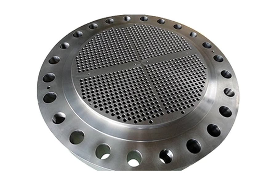
A tube-sheet design also needs the engineering information relevant to its intended equipment. Hole spacing and remaining ligaments are design matters; they should not be changed simply to suit an available drilling program.
Coordinate Material Condition with the Manufacturing Sequence
Specify the grade and required evidence
A purchase order should identify the material specification, grade, and required delivery condition. A description such as steel disc does not establish the properties, chemistry, or certification expected.
Where test material, prolongations, or attached samples are required, include them in the planning before forging. They may influence the supplied envelope and cannot always be added after the component is finished.
Keep traceability intact through stock removal. If the original marking area is machined away, agree how identification transfers to an approved remaining location or accompanying controlled record.
Account for treatment and residual stress
The route may include preliminary machining, thermal processing, and final machining. The placement of these stages depends on the component and its specified condition. Do not assume that every disc follows the same sequence.
The concept of residual stress explains why shape can change when material is removed even without an external service load. The amount and significance of movement depend on the actual part and manufacturing history.
Discuss whether intermediate checks or stabilization steps are required. The process owner should establish the route; the buyer should define the final requirements and any mandatory processing restrictions.
Distinguish rotating and stationary applications
A stationary cover and a rotating disc may have similar outside dimensions but different acceptance needs. Rotating service can require additional attention to the axis relationship, mass distribution, and specified balancing requirements.
State the relevant operating information when the supplier is expected to review suitability. If balancing is required, define the applicable procedure, acceptance basis, and condition of the component during the test.
Avoid assuming that balancing corrects geometric misalignment or an unsuitable structural design. It addresses a particular aspect of the rotating component and belongs within a broader specification.
Inspect the Disc at the Stage Where Each Requirement Applies
Check the incoming blank against its own requirements
Incoming inspection should establish material identity, relevant dimensions, surface condition, and specified examination results. Record whether the blank meets the agreed stock envelope before major machining begins.
For a rough-machined disc, measure the reference features that the next operation depends on. A blank may have ample overall material while still presenting an unsuitable preliminary bore or locating face.
Retain any approved deviations with the part records. A deviation accepted for one manufacturing route may not be acceptable if the buyer later changes the finished design or machining sequence.
Verify the finished relationships
Final inspection should follow the controlled drawing and its datum structure. The selected method must be capable of evaluating the feature, not merely convenient for the available equipment.
Define how the component is supported, especially where weight or compliance can influence measurements. If results are sensitive to temperature or installation condition, establish the relevant inspection conditions in advance.
Separate dimensional evidence from material and integrity records. A dimensional report cannot replace required material testing, and a material certificate cannot demonstrate the position of a drilled pattern.
Control rework and design changes
If machining exposes a discontinuity or insufficient stock, stop and obtain a documented disposition. Further removal can make a recoverable situation irrecoverable or move the part outside its approved envelope.
Changes to hole locations, finished thickness, or bore size should be approved by the responsible engineering authority. Record the revised drawing or concession so future orders do not inherit an undocumented modification.
Prepare the Forged Disc Order for a Clear Handover
A complete enquiry connects three things: the finished function, the purchased condition, and the remaining manufacturing work. Include a controlled drawing package and a scope statement that makes those relationships visible.
- Finished geometry: Identify the revision and functional interfaces.
- Blank envelope: State applicable dimensions, tolerances, and retained stock.
- Material state: Define grade, treatment, certification, and traceability.
- Manufacturing scope: List the machining and treatment operations included in delivery.
- Inspection stage: Assign checks to blank receipt, intermediate work, or final acceptance.
- Handling requirements: Establish lifting, surface protection, preservation, and packaging.
- Exceptions: Require written identification of any proposed departure.