
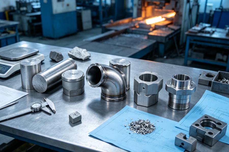
Improving material utilization in custom forged parts requires balancing billet size, geometry, forging route, machining allowance, and volume to reduce waste without compromising quality, grain flow, cost, or production stability.
Material Utilization in Forging
Material utilization describes how much of the original billet remains in the usable forged component after forging, trimming, scale removal, heat treatment, and machining.
A simplified calculation is:
Material Utilization = Final Part Weight ÷ Initial Billet Weight × 100%
Purchasing decisions are usually affected by the entire material route:
- Initial billet weight
- Heating and oxidation loss
- Flash and trimming loss
- Piercing or punching loss
- Test coupon allowance
- Rough machining removal
- Final machining removal
Main Causes of Material Loss
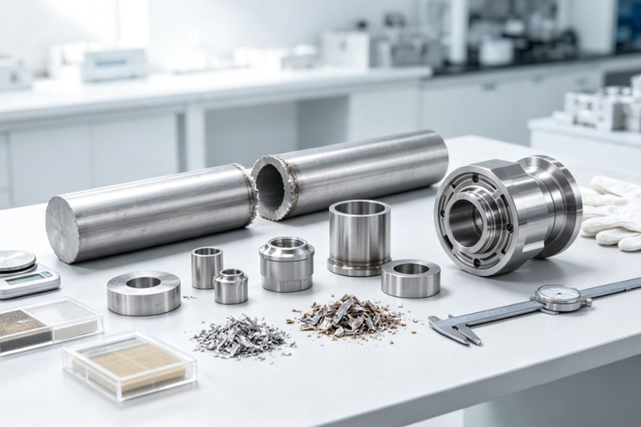
| Loss Source | Cause | Control |
| Oversized billet | Excess starting stock | Billet calculation |
| Heating scale | Surface oxidation | Furnace control |
| Forging flash | Excess die overflow | Die design |
| Punching loss | Bore material removal | Piercing route |
| End cropping | Billet end removal | Material preparation |
| Machining stock | Excess finishing allowance | Tolerance planning |
| Test material | Sampling allowance | Inspection planning |
| Rejected parts | Process defects | Process stability |
Flash is visible and easy to measure, while excess stock distributed across every surface may appear reasonable until total weight and machining hours are calculated.
Step 1: Finished Part
A common mistake is to begin process planning with standard bar dimensions or available stock sizes. This may simplify material purchasing, but it can also create unnecessary volume.
The optimal method involves reverse reasoning taking the finished component as the starting point.
The manufacturer should first identify:
- Finished dimensions
- Functional surfaces
- Machined and unmachined areas
- Required tolerances
- Grain flow direction
- Heat treatment condition
- Inspection and testing locations
Step 2: Forging Process
Material utilization depends heavily on whether the selected forging process follows the shape of the final component.
| Forging Process | Material Utilization Characteristics | Suitable Custom Forged Parts |
| Open-Die Forging | Flexible but may require more machining stock | Large shafts, blocks, cylinders, discs |
| Closed-Die Forging | Better shape control with flash around the parting line | Hubs, connecting parts, gear blanks |
| Flashless Forging | High material efficiency but strict billet control | Stable, high-volume precision parts |
| Ring Rolling | Efficient for annular shapes and large diameters | Bearing rings, flanges, gear rings |
| Roll Forging | Distributes material along the component length | Levers, axles, elongated parts |
| Upset Forging | Concentrates material in selected sections | Bolt heads, flanged shafts, stepped parts |
Step 3: Improve Billet Weight Calculation
Billet weight directly affects material utilization. Proper calculation balances part volume, machining allowance, flash, scale loss, and metal flow, reducing waste while preventing underfilling, dimensional variation, and unstable forging quality.
Step 4: Optimize Metal Distribution via Preform Design
Preforming determines how material enters and fills the final die cavity.
For Custom closed-die forgings with different wall thicknesses or cross-sections, a simple round billet may not distribute metal evenly. Certain regions suffer excessive material accumulation, whereas other sections experience insufficient filling during molding.
A suitable preform can:
- Move metal toward large-volume sections
- Reduce excessive flash around thin areas
- Improve die filling at corners and bosses
- Lower the risk of laps and folds
- Balance forging pressure
- Support the intended grain flow
Step 5: Reconsider the Value of Forging Flash
As metal flows into the narrow flash land, resistance increases inside the die cavity. This pressure helps fill difficult details and stabilizes the final shape. Reducing flash too aggressively may lower material consumption on paper while increasing underfilling or rejection risk.
Flash collected from continuous production runs acts as an indicator of drifting process parameters. Slow increases in flash weight often point to billet discrepancies, die deterioration or temperature fluctuations long before noticeable dimensional errors occur.
The important question is not whether flash exists, but whether its volume is appropriate.
Step 6: Improve Forging Accuracy
The largest saving is sometimes found after forging rather than during forging.
When rough forgings have wide dimensional variation, the machining department requires extra stock to ensure every part cleans up. Such dimensional tolerance safeguards manufacturing stability yet brings rises in:
- Raw material weight
- Cutting time
- Tool wear
- Chip volume
- Machine occupancy
- Handling time
Boosting the stability of forging processes enables safer cuts to machining stock.
Step 7: Coordinate Forging and Machining
Coordinating forging and machining improves material utilization by aligning datums, clamping, bore formation, allowances, and deformation control, reducing unnecessary stock, difficult setups, unstable machining, and costly rework during production planning.
Hollow Forging for Large-Bore Parts
Hollow parts deserve separate evaluation because their center material may represent a large portion of the billet.
| Route | Typical Material Utilization | Key Point |
| Solid forging + boring | 35%–60% | High center loss |
| Pierced hollow forging | 55%–75% | Reduced bore machining |
| Mandrel forging | 65%–85% | Suitable for large hollow parts |
| Ring rolling | 75%–90% | High efficiency for rings |
| Pre-drilled billet | 60%–80% | Requires bore control |
Although machining chips may be recycled, the buyer has already paid for the original alloy, heating, handling, forging, and machining of that metal.
Control Scale Loss
Controlling furnace temperature, holding time, reheating, and atmosphere reduces scale loss, surface damage, cleaning, and machining allowance while maintaining uniform billet heating and improving overall material utilization and production efficiency.
Match the Material Form to the Component
Selecting round, square, rectangular, hollow, or pre-pierced stock to match part geometry reduces deformation, crop loss, machining, and material waste while supporting grain flow, quality, volume, production efficiency, and consistency.
Step 8: Review Order Volume Before
Higher material utilization may require dedicated dies, preform tooling, piercing tools, or more precise billet preparation. Whether that investment is justified depends on production volume and material value.
- Prototype or one-off part
Use flexible tooling and controlled machining allowance
- Small batch
Improve billet size without overinvesting in dedicated dies
- Repeated medium volume
Develop preforms and reduce allowance through process data
- High-volume production
Evaluate closed-die, flashless, or automated billet control
- Expensive alloy material
Prioritize weight reduction even at lower production volume
- Very large forgings
Focus on hollow sections, near-shape forming, and machining reduction
Tips
Use Production Data Instead of Nominal Assumptions
Material improvement should be based on measured weights. At minimum, manufacturers can record:
- Purchased billet weight
- Cut billet weight
- Heated billet weight
- Trimmed forging weight
- Heat-treated forging weight
- Rough-machined weight
- Final component weight
- Scrap and rejection weight
Without these records, teams may focus on the most visible waste rather than the largest one.
Avoid Improving Utilization at the Expense of Quality
There is a practical limit to material reduction. Insufficient stock can cause:
- Unmachined surface exposure
- Dimensional shortage
- Incomplete die filling
- Poor grain flow
- Folding or laps
- Excessive die load concentration
- Unstable heat treatment dimensions
- Rejection during final inspection
Material efficiency should be viewed as a technical output instead of a separate purchasing requirement. The forging process needs to achieve steady performance first, and weight reduction can be realized via structured trials and mass production data.
Checklist
| Review Item | Key Question |
| Finished geometry | Does the forging shape follow the final component? |
| Forging method | Is the selected process suitable for the material distribution? |
| Billet size | Is billet weight based on calculated process losses? |
| Preform | Is metal positioned near high-volume sections? |
| Flash | Is flash sufficient but not excessive? |
| Bore formation | Can a hollow section be forged instead of machined? |
| Machining stock | Are allowances assigned by surface function? |
| Heating | Are temperature and holding time controlled? |
| Testing | Is test material located efficiently? |
| Production volume | Does the expected saving justify tooling investment? |
| Process data | Are component weights logged throughout each manufacturing stage? |
| Quality risk | Can stock be reduced without increasing rejection? |
Customers and producers can check factors above before locking in a forging process.
High material efficiency is achieved by balancing raw material savings against steady forging quality, streamlined machining and consistent manufacturing stability.