In nearly every rotating machine, the shaft transfers power, supports components, and maintains mechanical stability. From mining equipment and engines to compressors and gearboxes, its design directly affects torque transmission, fatigue life, vibration, and maintenance.
Step shafts, eccentric shafts, and crank shafts are common forged types. Although similar in appearance, they differ in geometry, stress distribution, function, and complexity. Selecting the wrong design can result in inefficiency and premature wear.
Understanding the Basic Design Principles
What Is a Step Shaft?
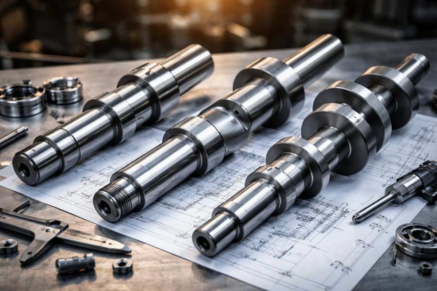
A step shaft is a concentric shaft featuring multiple changes in diameter along its length. These diameter transitions form shoulders that serve as mounting and positioning points for gears, bearings, pulleys, seals, and couplings. The central axis remains constant throughout the shaft, meaning there is no intentional offset in geometry.
Key structural characteristics include:
- Uniform central rotational axis
- Multiple stepped diameters
- Clear axial positioning surfaces
- Designed primarily for torque transmission
Step metal shafts are widely used in gearboxes, conveyor systems, rolling mills, pump drives, and power transmission assemblies. Because the design remains concentric, stress distribution is relatively predictable. Torsional stress dominates, with localized bending stress at shoulder transitions.
Proper fillet radii at diameter transitions are critical to reducing stress concentration and improving fatigue life. Forged step shafts benefit from continuous grain flow, which enhances mechanical strength compared to machined-from-bar alternatives.
What Is an Eccentric Shaft?
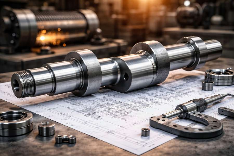
An eccentric shaft differs from a step shaft by incorporating an offset section. This offset means that a portion of the shaft rotates around an axis that is displaced from the main centerline. As the shaft rotates, the offset generates oscillating or reciprocating motion.
Defining features include:
- Single or limited offset journal
- Controlled eccentricity dimension
- Combined torsional and bending stresses
- Application-specific vibration output
The amount of eccentricity determines the amplitude of motion. Even minor deviations from design eccentricity can significantly affect system performance, particularly in vibratory machinery.
Eccentric shafts are commonly used in screening machines, crushers, compactors, feeders, and mechanical presses. The offset mass introduces radial loads and dynamic forces that must be carefully balanced to avoid excessive bearing stress.
The forging of eccentric shafts requires careful die design to ensure material flow supports the offset region without introducing internal defects.
What Is a Crank Shaft?
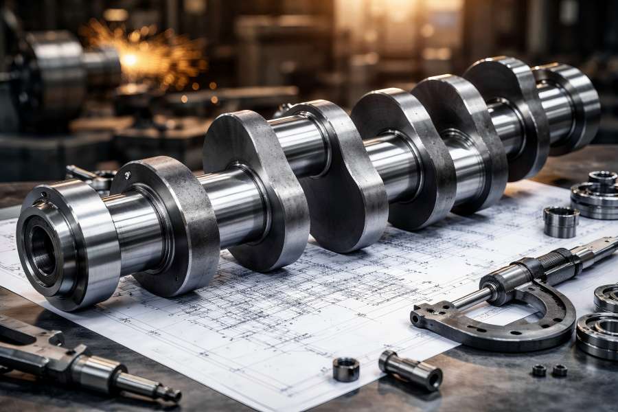
A crank shaft represents the most structurally complex of the three designs. It contains multiple offset crank throws connected by webs and supported by main journals. This geometry enables conversion between reciprocating motion and rotary motion.
Crank shafts typically include:
- Main journals
- Crank pins
- Web sections
- Counterweights
- Internal oil passages
They are crucial parts of hydraulic pumps, compressors, internal combustion engines, and heavy industrial equipment.
Each crank throw experiences cyclic bending and torsional stress as it converts motion. The fillet radius between journals and crank webs becomes a critical stress concentration point. Forged crank shafts are preferred for high-load applications because the forging process aligns grain flow along stress paths, increasing fatigue resistance.
Due to their complexity, crank shafts demand advanced forging, multi-stage machining, and precise dynamic balancing.
Structural Comparison
Geometry and Axis Alignment
The geometry of each shaft type defines its load-bearing capability and functional role.
| Shaft Type | Axis Alignment | Offset Feature | Relative Design Complexity |
| Step Shaft | Fully concentric | None | Low |
| Eccentric Shaft | Partially offset | Single offset | Medium |
| Crank Shaft | Multiple offsets | Multi-throw | High |
Step shafts maintain full concentric alignment, simplifying dynamic stability. Eccentric shafts introduce a single offset, increasing dynamic force. Crank shafts contain multiple offset sections, significantly increasing structural complexity.
Stress Distribution
Stress distribution differs substantially across the three designs.
- Step shafts primarily experience torsional stress. Shoulder transitions introduce stress concentration, but these can be minimized through optimized geometry.
- Eccentric shafts endure combined torsional and bending stress due to the offset mass. The rotating imbalance generates alternating radial forces.
- Crank shafts undergo the most severe loading conditions. Each crank throw experiences cyclic bending, torsion, and compression simultaneously. Fatigue performance becomes the dominant design concern.
Motion Output and Functional Role
| Shaft Type | Motion Output | Primary Function | Typical Use Case |
| Step Shaft | Pure rotation | Torque transmission | Gearboxes |
| Eccentric Shaft | Oscillation | Vibration generation | Screening equipment |
| Crank Shaft | Rotary + reciprocating | Motion conversion | Engines |
Selecting the wrong shaft design for the required motion type can compromise system efficiency.
Manufacturing Complexity Comparison
Forging Process Differences
Forging enhances mechanical strength by aligning grain flow and eliminating porosity. However, forging complexity varies.
- Step shafts can be produced through open-die or closed-die forging with moderate tooling requirements.
- Eccentric shafts require controlled die cavities to form the offset without internal stress defects.
- Crank shafts typically require precision closed-die forging. Multiple forging stages may be necessary to shape crank throws and counterweights accurately.
Forging temperature control and deformation rate significantly influence final mechanical properties.
Machining Requirements
Machining difficulty increases with design complexity.
- Step shafts require turning, milling of keyways, threading, and surface grinding.
- Eccentric shafts require offset turning operations and alignment verification.
- Crank shafts demand multi-axis CNC machining, drilling of oil passages, journal grinding, and dynamic balancing.
Machining time for crank shafts can be several times longer than for step shafts.
Heat Treatment and Surface Engineering
Heat treatment improves strength and fatigue resistance.
Common treatments include:
- Quenching and tempering for core strength
- Induction hardening for surface wear resistance
- Nitriding for improved fatigue performance
Crank shafts often undergo nitriding to enhance journal durability while preserving a tough core structure.
Material Selection Considerations
Material selection must align with operational loads, rotational speed, torque transmission requirements, fatigue cycles, and environmental conditions such as temperature, corrosion exposure, and lubrication quality. Choosing the correct shaft material directly impacts durability, reliability, and overall equipment lifespan.
Common shaft materials include:
- Medium carbon steel (e.g., 1045)
Widely utilized for general-purpose shafts because of its economical, machinable, and balanced strength. Suitable for moderate torque and standard industrial applications. - Alloy steel (e.g., 4140 or 42CrMo)
Offers higher tensile strength, improved hardenability, and superior fatigue resistance. Ideal for heavy-duty shafts operating under high torque and dynamic loads. - Micro-alloy steel (commonly used for automotive crankshafts)
Provides excellent fatigue strength and toughness without requiring extensive heat treatment. Frequently applied in high-volume automotive production for optimized performance and cost control.
Heat treatment improves mechanical properties by processes like quenching and tempering, induction hardening, and nitriding, enhancing surface hardness, wear resistance, and fatigue strength while preserving core toughness.
| Shaft Type | Typical Materials | Heat Treatment | Key Performance Target |
| Step Shaft | 1045, 4140 | Q&T | High torsional strength |
| Eccentric Shaft | 42CrMo | Q&T + Induction Hardening | Fatigue and wear resistance |
| Crank Shaft | 42CrMo, Micro-alloy steel | Nitriding | Cyclic durability & fatigue |
Crankshafts demand the highest fatigue resistance because they operate under continuous cyclic loading and stress reversal. Proper material selection combined with optimized heat treatment ensures long-term durability, crack resistance, and stable performance in high-speed rotating systems.
Performance Comparison
Fatigue Resistance
Fatigue resistance is critical for rotating components.
- Step shafts face moderate fatigue stress primarily from torsion.
- Eccentric shafts experience alternating bending stress due to offset rotation.
- Crank shafts endure high-frequency cyclic loading. Forged crank shafts significantly outperform cast designs in fatigue performance.
Torque Capacity
Torque capacity depends on diameter, material strength, and geometric design.
- Step shafts can be optimized for torque transmission by increasing critical section diameters.
- Eccentric shafts must balance torque transmission with offset geometry.
- Crank shafts transmit torque while converting motion, requiring robust web design.
Vibration and Dynamic Stability
- Step shafts offer stable operation with minimal inherent vibration.
- Eccentric shafts intentionally generate vibration; balancing is necessary to prevent structural overload.
- Crank shafts require precise counterweight balancing to control inertial forces.
Service Life and Reliability
Service life depends on load conditions, lubrication, and heat treatment quality.
In heavy-duty engines, forged crank shafts can operate reliably for thousands of hours under high cyclic stress.
Step shafts in industrial gearboxes often achieve long service intervals due to lower stress complexity.
Application-Based Selection Guide
Proper shaft selection depends on motion characteristics, load conditions, and system dynamics. Matching the shaft type to the application ensures optimal performance, service life, and mechanical efficiency.
Gearboxes and Industrial Transmission
Step shafts are ideal when the primary requirement is efficient torque transmission with stable rotational motion. They are commonly used in reducers, conveyors, and heavy-duty transmission systems where dimensional accuracy and torsional rigidity are critical.
Vibratory Machinery and Press Systems
Eccentric shafts are necessary when controlled oscillation or vibration is required. They are widely applied in vibrating screens, compactors, and mechanical presses, where converting rotational motion into periodic linear movement is essential.
Engines and Reciprocating Equipment
Crank shafts are essential for converting reciprocating motion into continuous rotational output. They function well under frequent cyclic loads and stress reversals in internal combustion engines, compressors, and pumps.
Key selection criteria include:
- Motion type (rotational, oscillating, reciprocating)
- Load magnitude and shock impact
- Speed range and dynamic balance requirements
- Operating environment (temperature, lubrication, corrosion)
- Maintenance strategy and expected service life
Cost and Return on Investment
Initial cost varies significantly across shaft types.
| Cost Factor | Step Shaft | Eccentric Shaft | Crank Shaft |
| Tooling Cost | Low | Medium | High |
| Machining Time | Low | Medium | Very High |
| Heat Treatment Cost | Moderate | Moderate | High |
| Inspection Requirement | Basic | Moderate | Extensive |
Crank shafts involve the highest production cost due to design complexity and strict quality control.
However, selecting a simpler shaft where appropriate can reduce unnecessary expenditure.
Comparative Overview
| Performance Factor | Step Shaft | Eccentric Shaft | Crank Shaft |
| Design Complexity | Low | Medium | High |
| Fatigue Stress Level | Moderate | High | Very High |
| Motion Conversion Capability | No | Partial | Full |
| Dynamic Balancing Requirement | Low | Medium | Critical |
| Manufacturing Cost | Low | Medium | High |
| Primary Industry | Transmission | Vibratory | Automotive |