In industrial manufacturing, clear and accurate technical drawings are essential for efficient and cost-effective production, especially in hot forging. They provide manufacturers with all necessary details to transform a design into a reliable, functional part.
Why Proper Technical Drawings Matter in Hot Forging
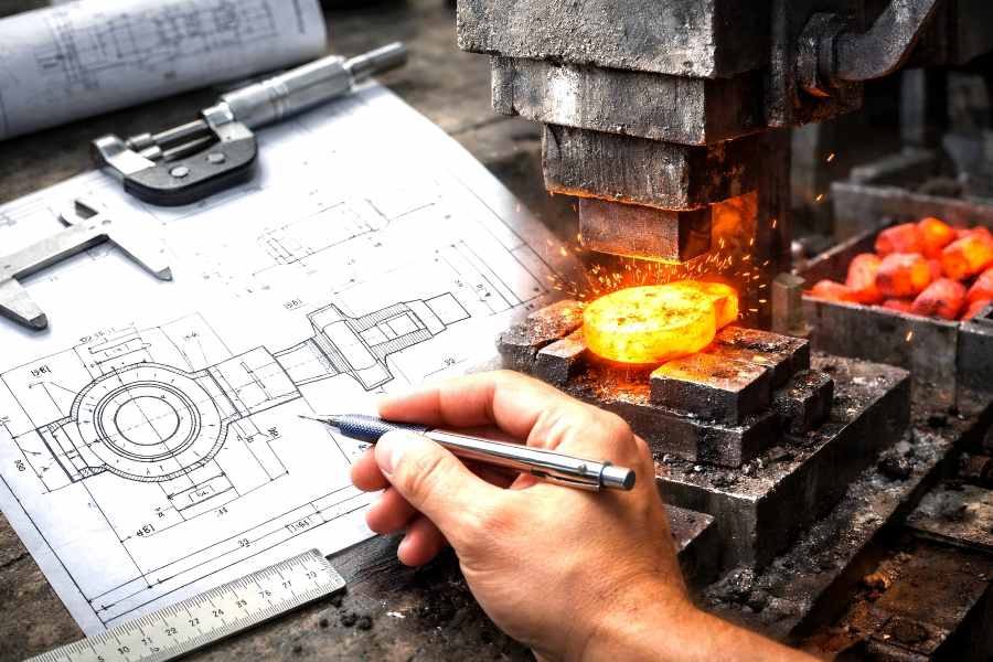
Hot forging is a process that applies compressive forces to metal heated to high temperatures, shaping it into durable components used in automotive, aerospace, energy, and heavy machinery sectors. The forging process involves complex deformation of material and precise tooling design, meaning any ambiguity in the drawing can create costly delays or defective parts.
Technical drawings are the common language used by manufacturers and designers. Product geometry, tolerances, surface finish specifications, material requirements, and special instructions are all defined by them. For hot forging, where dies are designed months in advance and tooling costs can be substantial, a well-prepared drawing ensures both parties understand expectations clearly and completely.
Recognizing the Fundamentals of Hot Forging Drawings
It’s crucial to comprehend the differences in hot forging designs before getting into the details:
- Process-Driven Geometry: Unlike machining, forging involves metal flow and deformation. Drawings often include forging allowances, fillet radii, and draft angles specific to die design.
- Material Behavior: Forged parts undergo grain flow changes, so drawings emphasize features that affect strength performance.
- Tooling Considerations: Many drawings must support die design, flash allowance, and trimming line requirements.
A technical drawing for forging isn’t just about dimensions — it’s about manufacturability and performance.
Section 1: Establish Clear Drawing Standards
Use a Consistent Drawing Template
Start with a consistent, professional drawing template that includes:
- Title block with company name, part number, revision status, and date
- Standard drawing scale
- Reference to applicable standards (e.g., ASME Y14.5 for GD&T)
- Revision history
- Sheet numbering for multi-page drawings
Consistency promotes clarity and speeds up review cycles with vendors.
Define Units and Scale
Clearly indicate whether measurements are in inches or millimeters — do not mix units on a single drawing. Choose a scale that best represents the part’s detail without crowding the sheet. For example, small features may require a 4:1 detail view.
List Applicable Standards
Include applicable industry standards on the drawing. Common references might include:
- Geometric Dimensioning and Tolerancing (GD&T) standards
- Surface finish standards
- Material specifications
- Heat treatment and testing specifications
Referencing standards prevents misinterpretation of symbols or tolerance requirements.
Section 2: Define Part Geometry Clearly
In forging, accuracy starts with the geometry. A technical drawing must convey every surface, hole, slot, and contour that affects tooling or performance.
Multiple Views for Comprehensive Geometry
Include multiple orthographic views:
- Front
- Top
- Right Side
- Isometric (optional but helpful)
Ensure that all critical features are visible in at least one view. If necessary, provide additional section views to expose internal geometry.
Use Section Views for Hidden Details
Section views are invaluable when internal features, cavities, or complex intersections cannot be clearly depicted in standard views. A section view cuts through the part and shows hidden geometry with hatch patterns.
Highlight Critical Features
Features that affect function — such as bearing surfaces, threaded holes, or locations where strength is essential — should be clearly called out with leader lines and notes.
Section 3: Dimensioning with Precision and Purpose
Dimensioning is the heart of the technical drawing. Accurate dimensional information tells the forging manufacturer the size, location, and allowable variation of every feature.
Follow Dimensioning Standards
Adhere to recognized dimensioning standards like ASME Y14.5. Standardized placement of dimensions and tolerances improves readability and prevents errors.
Avoid Redundant Dimensions
Dimensions should be unique and non-conflicting. Redundant or overlapping dimensions often cause confusion during manufacturing or inspection.
Use Datum References
Assign datum features to establish a framework for all dimensions. Datums anchor dimensions and tolerances relative to a defined reference — essential for parts that must mate with other components.
Dimension Key Functional Features First
Start dimensioning with features that directly affect function or assembly, then fill in secondary dimensions. Functional priorities include:
- Mounting hole centers
- Bearing surfaces
- Critical feature spacing
- Mating interfaces
Section 4: Tolerances and Geometric Controls
Forging tolerances are inherently broader than machining tolerances due to the nature of the process. However, designers must still communicate acceptable variations.
Specify Acceptable Tolerance Zones
To define, apply Geometric Dimensioning and Tolerancing (GD&T):
- Levelness
- Being straight
- The perpendicular
- Concentrated
- The runout
GD&T allows precise control over part variation without over-specifying tolerances that drive up cost.
Balance Precision with Cost
Tight tolerances increase inspection effort and cost. Work with your forging partner to establish tolerances that meet design function without unnecessary manufacturing burden.
Include Tolerance Notes
General tolerance notes can be applied for features that don’t require special controls. For example:
- Unless otherwise specified, ±0.5 mm on non-critical dimensions
- Angular tolerances ±1°
Section 5: Material and Heat Treatment Specifications
Material selection and heat treatment directly influence forging performance, ductility, and strength. The technical drawing must clearly specify both.
Material Designation
Include a complete material callout that covers:
- Material type (e.g., alloy grade)
- Specification reference (e.g., ASTM number)
- Condition (if applicable)
For example: Material: Alloy Steel ASTM A314 Grade B
Heat Treatment Requirements
Indicate the necessary heat treatment procedures, such as:
- Normalizing Annealing
- Tempering and quenching
- Relieving stress
Include target hardness or mechanical property ranges (e.g., Rockwell C scale or tensile strength).
Surface Treatment Post-Forging
If surface treatment is needed after forging, clearly specify the process and requirements on the drawing.
Section 6: Surface Finish and Feature Control
The drawing should describe how smooth or rough each surface must be. Surface finish symbols communicate this without ambiguity.
Use Standard Surface Finish Symbols
Apply industry-standard finish symbols next to corresponding surfaces. Specify values in microinches or micrometers based on project norms.
Identify Functional Surfaces
Surfaces that interact with other parts — such as sealing faces or bearing areas — often require better finish control than non-critical surfaces.
Section 7: Notes and Special Instructions
A dedicated notes section on the drawing allows you to convey additional manufacturing, inspection, or handling requirements.
General Notes
Include notes that apply to the entire part, such as:
- Remove all burrs
- Deburr sharp edges
- Break sharp corners with specified radius
Process Specific Notes
For forging, you may want to include:
- Forge orientation or preferred faces
- Required flash allowance
- Die parting line preferences
- Trimming or machining allowances
These instructions help the forging vendor plan tooling and process flow efficiently.
Section 8: Indicating Machining Allowances
Forged parts often require secondary machining to achieve final geometry or precision features. When machining is expected, show allowances on the drawing.
Call Out Machining Allowances
Use clear annotation to describe how much material should be left for finishing. For example:
- +2.5 mm machining allowance on all OD surfaces
- +1.0 mm on critical bore surfaces
Coordinate with Vendor
Discuss machining allowances with the forging partner early. Too little allowance increases risk of under-sized finished parts; too much adds unnecessary cost.
Section 9: Revision Control and Document Distribution
Professional drawings undergo changes. Managing revisions carefully ensures all stakeholders work with the latest information.
Revision Block Standards
Include a revision block that shows:
- Revision letter or number
- Description of changes
- Date
- Approver’s initials
Version Control Practices
- Control and archive older revisions
- Distribute changes promptly to vendors and internal teams
- Ensure approval signatures where required
Section 10: Communicating with Your Hot Forging Manufacturer
A technical drawing is not a stand-alone document. It’s part of a larger communication process between your design team and the forging vendor.
Early Engagement
Share preliminary drawings early in the tooling and planning phase. Early feedback from the forging manufacturer can reveal:
- Manufacturing feasibility concerns
- Suggestions to simplify forming
- Potential cost-saving modifications
Early engagement prevents late changes that drive up cost and delay delivery.
Review and Clarification Sessions
Consider virtual or in-person review sessions with the vendor to walk through the drawing. These sessions align expectations and reduce assumptions.
Ask for Vendor’s Drawing Input
Some forging manufacturers provide their own drawing templates or request specific callouts for forging processes. Be willing to adapt your drawing to their workflow when appropriate.
Section 11: Common Mistakes to Avoid in Forging Drawings
Even experienced designers can make missteps when preparing forging drawings. The following are common dangers and strategies for avoiding them:
Incomplete Views
Not showing all critical surfaces leads to assumptions by the manufacturer. Use section views and detail inserts wherever necessary.
Overly Tight Tolerances
Specifying tight tolerances where they’re not needed adds cost and increases rejection rates. Apply tighter controls only where function demands.
Missing Material or Heat Treatment Information
Omitting full material specifications or heat treatment details can lead to incorrect or sub-par materials being used.
Ignoring Machining Allowances
Failing to show machining allowances risks parts being finished undersize.
Using Ambiguous Symbols
Non-standard or poorly placed symbols confuse manufacturing teams. Stick to recognized drafting standards throughout.
Section 12: Best Practices for Review Before Submission
Before sending a drawing to a hot forging manufacturer, run it through a thorough internal review process.
Peer Review
Have a colleague or engineer not involved in the drawing creation review it for:
- Missing details
- Conflicting dimensions
- Ambiguous symbols
- Omissions in notes or views
Fresh eyes often catch mistakes the original drafter overlooks.
Simulate Manufacturer Interpretation
Walk through the drawing step by step as if you are the vendor. Ask yourself:
- Can each feature be made from this drawing alone?
- Are tolerances justified?
- Are material and processing requirements clear?
Use Checklists
Develop an internal checklist covering all required sections of the drawing. Checklists standardize quality and reduce oversights.
Section 13: Leveraging CAD Tools for Accuracy and Consistency
Modern CAD systems like SOLIDWORKS, AutoCAD, or CATIA support advanced drawing creation. Use built-in tools to:
- Generate automatic dimensioning
- Apply standard symbols
- Link part models to drawing views
- Maintain drawing databases for easy updates
When CAD and PLM systems are integrated, changes cascade automatically to all stakeholders, reducing manual errors.
Section 14: Incorporating 3D Models and Digital Files
While 2D drawings remain the standard for manufacturing, 3D models add clarity and reduce interpretation errors.
Include 3D Model Files
Attach or share:
- STEP files
- IGES files
- Native CAD assemblies
3D models allow forging manufacturers to examine the part in three dimensions, improving understanding of complex geometry.
Use Digital Markups During Review
Digital markups allow comments and revisions to be shared clearly with version control, speeding up review cycles and eliminating paper errors.