For piping systems to be safe, effective, and long-lasting in sectors like oil and gas, chemical processing, power generation, and water treatment, metal pipe fittings must be the proper size. Although seemingly simple, fitting sizes are often misunderstood due to nominal dimensions, differing standards, and schedule variations.
Basic Concepts of Pipe and Fitting Sizes
Understanding metal pipe fitting sizes begins with recognizing that most sizing systems are nominal, not literal.
Nominal vs Actual Dimensions
Pipe and fitting sizes are generally referenced by a nominal size, which serves as a standardized identifier rather than a precise measurement. For instance, the outside diameter of a “2-inch” pipe is not precisely 2 inches. Instead, the nominal designation allows consistency across materials, wall thicknesses, and pressure ratings.
Relationship Between Pipe and Fitting Sizes
Metal pipe fittings are sized to match the nominal size of the pipe, not its actual measured diameter. This ensures that fittings such as elbows, tees, and reducers align properly regardless of pipe schedule, as long as the nominal size is the same.
Metric and Imperial Systems
Globally, two main systems are used:
- NPS (Nominal Pipe Size): Inch-based system primarily used in North America
- DN (Diameter Nominal): Metric-based system used internationally
Although NPS and DN values are often paired (e.g., NPS 2 ≈ DN 50), they are not direct conversions but standardized equivalents.
Key Dimensions Used in Metal Pipe Fittings
Several dimensional parameters define how a pipe fitting connects, aligns, and performs.
Nominal Diameter (NPS / DN)
Nominal diameter is the standardized size designation used for both pipes and fittings. It ensures compatibility across components even when the wall thickness varies.
Outside Diameter (OD)
The outside diameter is the actual measured external diameter of the pipe. For a given NPS, the OD remains constant regardless of schedule, making it a critical reference for fitting, fabrication, and alignment.
Inside Diameter (ID)
Inside diameter is calculated as:
ID = OD − (2 × wall thickness)
Since wall thickness changes with schedule, the ID varies, directly affecting flow capacity and velocity.
Wall Thickness
The mechanical strength and pressure rating of the pipe are determined by the wall thickness. Pipe fittings must match or exceed the pipe’s wall thickness to maintain structural integrity.
Center-to-End and Face-to-Face Dimensions
These dimensions define the physical length of fittings:
- Center-to-End: Distance from the fitting centerline to the end connection
- Face-to-Face: Distance between two connecting faces (commonly for flanged fittings)
Pipe Schedules and Wall Thickness
Wall thickness is indicated by a dimensionless integer called pipe schedule. Higher pressure ratings and thicker walls are correlated with higher schedule numbers.
Common Pipe Schedules
| Schedule | Typical Application |
| Sch 10 | Low-pressure, corrosion-resistant systems |
| Sch 20 | Light industrial services |
| Sch 40 | General-purpose industrial piping |
| Sch 80 | High-pressure applications |
| Sch 160 | Extreme pressure and temperature |
Impact on Fittings
While the OD remains constant, fittings must be produced to match the wall thickness of the pipe schedule. Butt weld fittings, in particular, must have compatible wall thicknesses to ensure proper welding and stress distribution.
Standard Pipe Size Charts Explained
Pipe size charts provide the dimensional foundation for selecting fittings. These charts relate nominal sizes to actual wall thicknesses, internal diameters, and exterior diameters.
Table 1: NPS–DN Conversion (Common Sizes)
| NPS (inch) | DN (mm) | Outside Diameter (mm) |
| 1/2 | 15 | 21.34 |
| 1 | 25 | 33.40 |
| 2 | 50 | 60.33 |
| 4 | 100 | 114.30 |
| 6 | 150 | 168.28 |
| 8 | 200 | 219.08 |
| 12 | 300 | 323.85 |
| 24 | 600 | 609.60 |
This table highlights an important reality: DN values are rounded nominal numbers, while outside diameters follow precise imperial or metric standards.
Table 2: Typical Schedule 40 vs Schedule 80 Dimensions (Example)
| NPS | Schedule | Wall Thickness (mm) | Approx. ID (mm) |
| 2 | 40 | 3.91 | 52.5 |
| 2 | 80 | 5.54 | 49.3 |
| 6 | 40 | 7.11 | 154.1 |
| 6 | 80 | 10.97 | 146.3 |
These differences illustrate how the internal diameter decreases significantly with thicker schedules, even though OD remains constant.
Metal Pipe Fittings: Types and Size Considerations
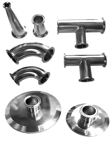
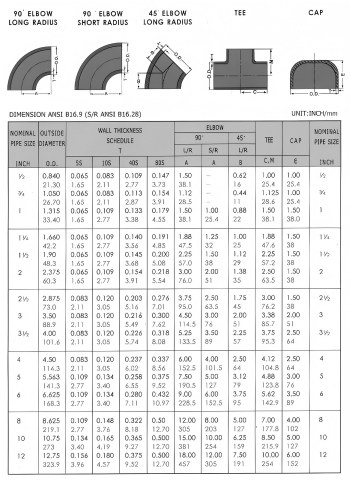
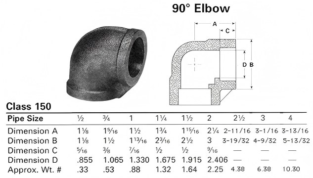
Elbows (45°, 90°, and 180°)
Elbows are one of the most popular fittings because they alter the direction of flow. Size considerations include nominal size, schedule, and radius.
The centerline radius of long-radius elbows is 1.5 times the pipe size. The radius of short-radius elbows is equivalent to the pipe’s nominal size. Long-radius elbows reduce pressure drop and turbulence, making them preferable for flow-critical systems.
Elbows must match pipe OD and schedule to ensure weld alignment and internal smoothness.
Tees and Crosses
Tees split or combine flow paths. Equal tees have the same nominal size on all outlets, while reducing tees have a smaller branch size.
Sizing reducing tees requires careful attention. The branch OD must match the corresponding pipe OD, and wall thickness transitions must comply with standards to avoid stress concentrations.
Cross fittings are less common due to flow imbalance and stress issues, but follow similar sizing principles.
Reducers
Reducers are used to join pipes of various sizes. Concentric reducers are usually utilized in vertical lines and preserve a common centerline. on order to prevent air pockets, eccentric reducers are preferable on horizontal lines and preserve one flat side.
Reducers are sized by listing the large end size first, followed by the small end size, along with the schedule.
Couplings, Unions, and Caps
Couplings join two pipes of the same size, while reducing couplings join different sizes. Caps close pipe ends. Size selection depends on nominal pipe size and connection type, with threaded and socket-weld variants having different dimensional requirements.
Connection Types and Their Size Implications
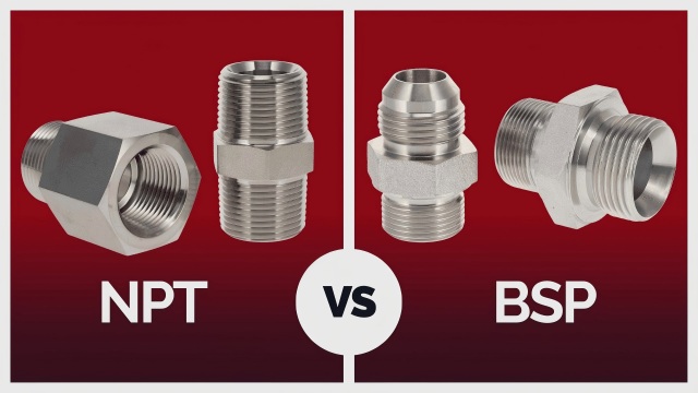
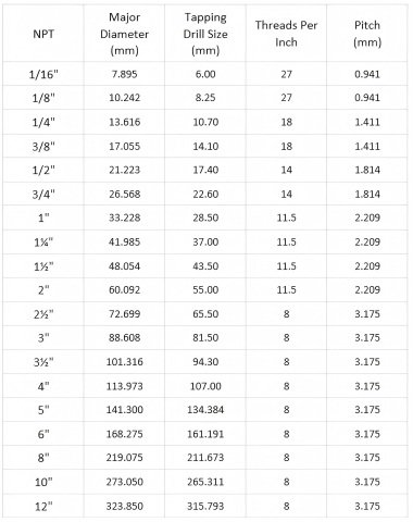
Threaded Fittings
Threaded fittings rely on standardized thread forms such as NPT, BSPP, and BSPT. The pipe size, not the thread OD, is referred to as nominal size. Misidentifying thread standards is a common cause of leaks and assembly failures.
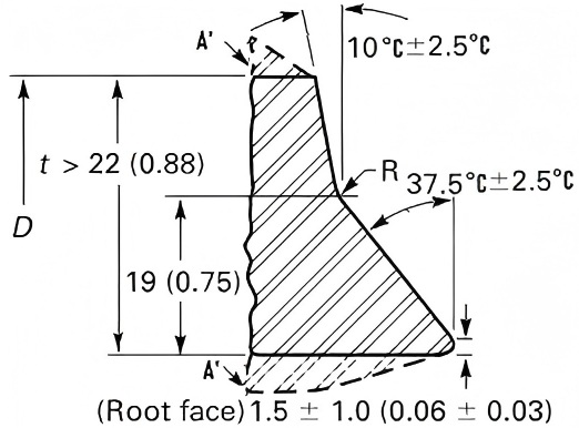
Butt-Weld Fittings
Butt-weld fittings are sized to match pipe OD and schedule. End bevel angle, root face, and bore alignment are critical dimensional parameters defined by standards.
Socket-Weld Fittings
A recessed socket is used in socket-weld fittings, where the pipe is inserted. Weld quality depends on appropriate clearance and insertion depth. Usually, these fittings are utilized in systems with higher pressure and smaller diameters.
Flanged Connections
The nominal pipe size and pressure class determine the size of flanges. Bolt hole patterns, raised face dimensions, and thickness vary with pressure rating. The flange bore must align with the pipe ID for smooth flow.
Global Pipe Fitting Size Standards
Different regions use different dimensional standards, but all aim for interchangeability.
ASME standards dominate in North America and many international projects. ISO standards provide metric equivalents used globally. While JIS standards are widely used in Japan, DIN standards are more common in Europe.
While OD compatibility allows mixing components in many cases, wall thickness series and tolerances differ. Engineers must always verify dimensional compatibility rather than relying solely on nominal size markings.
Industry Applications and Typical Size Ranges
| Industry Application | Typical Size Range | Common Schedule / Rating | Key Material Characteristics |
| Oil & Gas | 2″–48″ | Sch 40 / 80 / 160 | High-strength carbon steel, alloy steel for high pressure |
| Chemical Processing | 1″–24″ | Sch 10 / 40 | Corrosion-resistant stainless steel and special alloys |
| Power Plants | 2″–36″ | Sch 40 / 80 / XXS | High-temperature alloy steels and creep-resistant materials |
| Water Treatment | ½″–48″ | Sch 10 / 40 | Wide material selection for corrosion and cost efficiency |